How to Weld Brass with MIG: Instructions, Tips, and Useful Advice
You can weld some brass alloys with MIG, but it is difficult and often inferior to TIG or brazing because brass conducts heat quickly and zinc can vaporize.
Brass is a copper-and-zinc alloy so joining it with a MIG welder involves more than choosing a wire and pulling the trigger The alloy s high thermal conductivity.
That makes the process part of a larger decision identify the brass assess the joint select a compatible filler prepare the metal control heat and then inspect the. This guide examines “how to weld brass with mig” and explains the details that matter in practice.
- ✓MIG welding brass is possible for selected alloys and noncritical repairs, but it is less forgiving than TIG or brazing.
- ✓Clean, identify, and firmly support the brass before welding; contamination and poor heat control quickly cause defects.
- ✓Use a compatible copper-based filler, shielding gas, short arc control, and the lowest heat that achieves fusion.
- ✓Zinc fumes are a serious hazard, so effective ventilation, respiratory protection, and fire-safe preparation are essential.
- ✓Test on matching scrap first and reject the process if the joint needs high strength, pressure integrity, or precise appearance.
Can You Weld Brass With MIG?
Yes but the answer depends on the alloy thickness joint design and purpose of the repair MIG can deposit a copper-based filler onto brass yet it may produce.
Many brass components contain different proportions of copper zinc lead tin or other additions Free-machining brass may contain lead and should not be heated casually while unknown scrap.
- Suitable project: A small, noncritical bracket, decorative repair, or thick brass part that can be tested first.
- Use caution: Thin sheet, cast brass, unknown alloy, parts exposed to pressure, and assemblies containing oil or plating.
- Choose another process: Use brazing or TIG when appearance, control, leak resistance, or mechanical reliability matters.
MIG welding versus brazing
MIG welding normally creates fusion by melting the base metal and filler together Brazing joins parts with a filler that melts below the base metals allowing the brass.
For many brass repairs brazing is the practical first choice It can fill a properly fitted joint without aggressively melting the brass MIG becomes more reasonable when equipment.
MIG welding versus TIG
TIG offers a smaller more controllable heat source and lets the operator add filler independently of arc energy That control is valuable on brass particularly around edges or.
Neither process automatically solves alloy compatibility. A clean joint, suitable filler, correct shielding, and controlled heat remain necessary whether the arc comes from a spool gun, standard MIG torch, or TIG torch.
How to Weld Brass With MIG: Equipment and Filler Choices
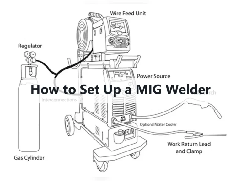
The equipment must deliver stable low-to-moderate output and a consistent wire feed. A standard steel MIG setup may work mechanically, but the wire, liner, contact tip, polarity, shielding gas, and torch access must all suit the chosen copper-based filler.
There is no universal setting for brass because a thin decorative fitting and a thick cast component absorb heat differently Begin with the filler manufacturer s data when.
- Power source: Confirm that the machine can run the selected wire and maintain a stable arc at the required low end.
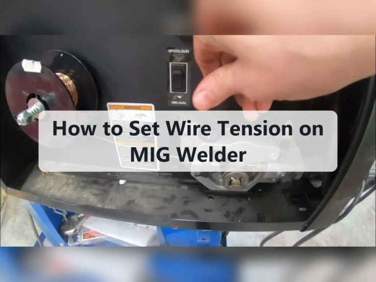
- Wire path: Copper-based wire can be softer than steel wire, so use suitable drive rolls, liner support, and moderate feed tension.
- Shielding: Use a clean, consistent shielding gas appropriate for the filler and process; drafts can immediately contaminate the arc.
- Consumables: Match the contact tip and liner to the wire diameter, and replace worn parts that cause irregular feeding.
Choosing the filler metal
A copper-silicon filler commonly identified in welding catalogs as a silicon-bronze type is often considered for joining copper-based alloys It can flow well and may support a lower-heat.
Other copper-based wires may be appropriate for particular brass compositions but filler selection should not be based only on color The filler must be compatible with the base.
Gun, liner, and drive-roll setup
Soft or relatively flexible copper-alloy wire can bird-nest if the feed path has excessive resistance. Keep the torch cable as straight as possible, use appropriate drive rolls, and set only enough tension to feed consistently without flattening the wire.
A shorter gun-to-work distance can improve arc control but the exact distance depends on the wire and transfer mode Keep the nozzle clean check gas flow at the.
Shielding gas and polarity
Shielding gas protects the hot puddle from oxygen and nitrogen The correct gas depends on the filler and welding mode a gas selected for mild steel may produce.
Polarity also follows the wire manufacturer’s instructions. Confirm it before striking an arc, because incorrect polarity can cause an erratic arc, poor penetration, excess spatter, or a bead that appears deposited but is not properly bonded.
Prepare Brass Before MIG Welding
Preparation often determines the result before the machine is switched on Brass surfaces may carry lacquer oil oxide fingerprints plating paint polishing compound or machining residue Heating those.
Identify the joint and establish whether the part actually needs fusion A close-fitting lap or fillet joint may be more forgiving than a wide gap while a butt.
- Clean mechanically: Remove coatings and oxidation with a dedicated stainless brush, abrasive, or suitable method reserved for clean copper alloys.
- Degrease safely: Use an appropriate nonchlorinated cleaner, let the surface dry fully, and never weld over solvent residue.
- Control the fit: Keep the joint consistent and minimize unnecessary gaps that demand extra filler and heat.
- Expose clean metal: Remove plating or unknown surface treatments in the weld zone while planning for the resulting fumes and waste.
Cleaning and surface preparation
Use separate abrasives and brushes for brass whenever possible Tools previously used on carbon steel can embed iron. This distinction matters when answering “how to weld brass with mig”.
Do not assume a shiny surface is clean. Polishing compounds can remain in scratches, and lacquer may become nearly invisible after sanding. If the part has plating, paint, or an unknown finish, determine what it is before heating it.
Joint design and fit-up
A sound fit reduces the volume of molten material and limits the heat needed to bridge the joint For a repair remove cracked or porous material until clean.
Use tack welds sparingly and place them symmetrically when practical Brass expands and contracts differently from steel fixtures so rigid clamping can pull the joint apart or leave.
Preheating: helpful but easy to misuse
Preheating can reduce the temperature difference between the arc area and the rest of a thick part but it also raises the overall heat level and may increase.
If preheating is used, apply it evenly and monitor the part with a suitable temperature-control method. Avoid guessing by color, because brass can change appearance and hot metal can cause severe burns without looking obviously hot.
Step-by-Step MIG Procedure for Brass
A controlled procedure is more reliable than trying to compensate for defects after they appear First determine whether the joint is suitable then set up ventilation prepare the.
The goal is a small, fluid puddle that wets both sides of the joint without boiling, collapsing, or spreading heat far beyond the repair. Move steadily and stop if the surface becomes excessively bright, porous, or visibly loses material.
- Test first: Confirm wire feed, gas coverage, polarity, and heat response on similar scrap.
- Start cool: Use the lowest practical heat and increase gradually only when the filler will not wet the joint.
- Use short runs: Deposit small sections, allow cooling, and alternate locations to limit distortion.
- Inspect as you go: Stop for contamination, cracks, pinholes, or a deteriorating puddle instead of burying defects.
- Secure the work. Place the brass on a stable, fire-resistant surface and arrange clamps, backing, and torch access before welding. Confirm that the work lead makes clean electrical contact with the part or an appropriate fixture.
- Set up ventilation and protection Position local exhaust to draw fumes away from your breathing zone.
- Check the machine. Install the correct wire, contact tip, liner, drive rolls, gas, and polarity. Set gas flow according to the equipment and filler guidance, then check for leaks and drafts.
- Run a test bead. Practice on matching scrap in the same position and with similar thickness. Look for a stable arc, consistent wire feed, reasonable wetting, and minimal spatter before moving to the actual part.
- Establish the arc at the joint. Use a controlled torch angle and keep the arc directed so both sides of the joint receive enough heat. Avoid a long, wandering arc, which increases oxidation and makes the puddle difficult to manage.
- Travel smoothly. A short, consistent bead is usually safer than a slow, wide weave. Pause only enough for the filler to wet the edges, then keep moving before the brass overheats.
- Use intermittent welding. On a heat-sensitive part, weld a short segment, move to a separated area, and allow the first segment to cool. This sequence reduces accumulated heat and can preserve alignment.
- Stop before the joint deteriorates. If the metal begins to slump, spit, smoke heavily, or develop a rough porous surface, release the trigger and let the part cool. Correct the cause before resuming.
- Allow controlled cooling. Do not quench a hot brass weld unless a qualified procedure specifically requires it. Sudden cooling can increase stress and may distort or crack the joint.
- Clean and inspect. Remove residue only after the part is cool enough to handle. Examine the bead, edges, underside when accessible, and surrounding brass for cracks, incomplete bonding, pinholes, or burn-through.
Technique adjustments that matter
Keep the torch movement deliberate and avoid excessive weaving A slight travel angle can help place filler at the leading edge of the puddle but the exact angle.
Short-circuit-style control may be useful on thinner work if the machine and wire support it while higher-energy transfer can overwhelm brass Listen for a consistent arc and watch.
When filler appears to sit on top
A bead that resembles a raised strip may have poor bonding Possible causes include oxide oil insufficient heat excessive travel speed incorrect polarity or an unsuitable filler Increase.
Safety Hazards When MIG Welding Brass
Brass welding requires more than ordinary arc-welding precautions The zinc in many brass alloys can vaporize in the arc and condense as fine metal fume The visible plume.
Ventilation must capture fumes at their source rather than merely moving shop air Respiratory protection if required should be selected through a proper workplace hazard assessment and fit.
- Fume control: Use local exhaust positioned close enough to capture emissions without disturbing shielding gas.
- Unknown alloys: Stop and identify plated, painted, leaded, or contaminated brass before applying heat.
- Fire prevention: Remove combustible materials, drain flammable liquids, and check the area for hot-metal ignition risks.
- Skin and eye protection: Protect against ultraviolet radiation, spatter, hot fixtures, sharp edges, and heated cleaning chemicals.
Lead, plating, and contamination concerns
Some brass products contain lead to improve machinability. Heating them can create additional exposure concerns, and ordinary shop ventilation may not be enough. Plated parts may release coating fumes or reveal a different base metal beneath the surface.
Never weld a container, pipe, fitting, or machine component that has held fuel, solvent, refrigerant, oil, or another flammable substance until it has been professionally cleaned and declared safe. Residual vapors can ignite violently even when the container appears empty.
Protecting the finished part
After welding, wash or wipe away residues using a method compatible with the alloy and the service environment. Do not grind aggressively until the metal has cooled, and avoid breathing dust created by grinding a contaminated or lead-containing part.
If the component will contact drinking water, food, medical equipment, or corrosive chemicals, confirm that the filler and surface treatment are appropriate. A visually attractive weld is not proof of chemical suitability or structural integrity.
Common MIG Brass Welding Problems and Fixes
Brass defects usually result from a combination of heat surface condition arc behavior and alloy chemistry Diagnose the. Keep these limitations in mind when considering “how to weld brass with mig”.
Some defects cannot be repaired by adding another bead. Porosity, cracks, and incomplete fusion may continue beneath a cosmetic cover, especially if the underlying brass has boiled or the joint was contaminated.
- Too much heat: Produces burn-through, distortion, zinc loss, and a rough or porous bead.
- Too little heat: Leaves filler sitting on the surface with weak edge bonding.
- Poor cleaning: Traps oil, oxide, coating, or polishing residue in the weld.
- Long continuous beads: Accumulate heat until the joint collapses or warps.
| Observed problem | Likely causes | Useful checks |
|---|---|---|
| Porous, pinholed bead | Contamination, poor gas coverage, zinc vapor, drafts, excessive heat | Clean again, inspect gas flow, block drafts, shorten the run, and lower heat if possible |
| Filler does not wet edges | Oxide, insufficient heat, wrong polarity, fast travel, incompatible filler | Verify setup, improve fit and cleaning, then make a small controlled adjustment |
| Burn-through or sagging | Thin brass, excessive amperage, slow travel, large gap | Reduce heat, shorten beads, tighten the fit, and use backing if suitable |
| Wire bird-nesting | Excessive drive tension, restricted liner, misaligned rolls, soft wire | Check the complete feed path and use the correct rolls and liner |
| Cracking near the weld | Rigid restraint, unsuitable alloy or filler, rapid cooling, contamination | Review joint design, allow controlled cooling, and reconsider the joining process |
Porosity and dark surface deposits
Porosity can come from gas disruption dirty metal or vaporized zinc Check the nozzle gas hose regulator torch.
Distortion and loss of shape
Brass expands noticeably with heat, and thin sections can move before the weld is complete. Use a close fit, balanced tacks, intermittent welds, heat sinks where appropriate, and a sequence that distributes heat rather than concentrating it at one end.
Weak-looking or weak-feeling joints
A smooth bead can still have incomplete fusion or insufficient throat thickness Check the joint from every accessible side and use a destructive test on a duplicate sample.
When MIG Is the Wrong Choice for Brass
Process selection should follow the job s consequences not just the equipment already in the workshop If failure.
Even a successful test bead may not represent service performance. The actual part may have a different alloy, heat treatment, wall thickness, restraint condition, or contamination history. Treat testing as evidence about feasibility, not automatic qualification for every brass component.
- Use brazing: The part is thin, distortion-sensitive, or better served by lower-temperature joining.
- Use TIG: You need precise heat control, a clean appearance, or careful filler placement.
- Seek a qualified procedure: The joint is structural, pressure-bearing, repeatedly loaded, or difficult to inspect.
- Replace the part: The brass is cracked throughout, severely dezincified, porous, or contaminated beyond safe preparation.
Pressure and structural applications
Brass valves, fittings, hydraulic components, heat exchangers, and pressure vessels deserve special caution. A surface-level repair can leak under pressure or fail after thermal cycling even if it looks sound immediately after welding.
Use the original manufacturer’s repair guidance when available. If none exists, involve a qualified welding professional who can identify the alloy, select the procedure, determine inspection requirements, and evaluate whether repair is technically and legally appropriate.
Decorative and thin brass
Thin decorative brass often benefits from silver brazing soft soldering where appropriate or TIG with very careful control MIG wire may deposit too quickly and create a heavy.
For visible work, make a sample that includes the same edge geometry and surface finish. The final appearance depends not only on the bead but also on cleaning, grinding, blending, polishing, and any protective coating applied afterward.
Inspect, Finish, and Maintain a Brass MIG Repair
Let the part cool naturally enough to handle then remove spatter and residue without gouging the surrounding brass Avoid using a finishing operation to disguise a crack crater.
Inspection should match the consequence of failure. A decorative bracket may need careful visual inspection and a fit check, while a pressure fitting may require leak testing, dimensional checks, or professional nondestructive examination.
- Surface: Look for cracks, pinholes, undercut, crater holes, trapped slag-like residue, and excessive spatter.
- Geometry: Confirm that the part remains aligned and that heat has not changed critical dimensions.
- Bond: Check accessible edges for wetting and incomplete fusion rather than judging the bead’s height alone.
- Service test: Use an appropriate controlled test before returning a repaired part to load, pressure, heat, or vibration.
Cleaning and corrosion protection
Remove flux or chemical residue if a preceding brazing or cleaning operation used it. Even when MIG is used without flux, fingerprints, abrasive dust, and dissimilar-metal particles can affect the appearance and corrosion behavior of the repair.
Brass can tarnish and the weld area may develop a different color from the base metal because of.
Monitoring the repair in service
For a noncritical repair, inspect the area after the first period of use and again after significant thermal or mechanical cycling. Watch for discoloration, weeping, new cracks, looseness, or distortion around the joint.
Do not continue using a repaired component merely because it survived one initial test. Repeated vibration and temperature changes can reveal defects that were not visible when the metal was freshly finished.
FAQ: How to Weld Brass With MIG
Is MIG welding brass as strong as welding steel?
Not necessarily Brass has different thermal and metallurgical behavior and the strength of the joint depends on the alloy filler fusion quality geometry and service conditions A brass.
What wire should be used for brass MIG welding?
A compatible copper-based filler often a silicon-bronze type may be suitable for selected brass joints The correct choice depends on the brass alloy.
Can a regular steel MIG welder weld brass?
The power source may be usable, but the complete setup must support the selected filler. Check wire-feed components, liner, drive rolls, contact tip, shielding gas, polarity, and low-end arc stability. A steel-only setup may produce poor feeding or an unsuitable arc.
Why does brass make so much smoke when MIG welded?
Heat can vaporize zinc and other surface or alloy constituents, creating metal fumes. Excessive heat, coatings, oil, plating, or poor ventilation can increase the visible plume. Stop if fume control is inadequate and improve source capture before continuing.
Can thin brass sheet be MIG welded?
It can be attempted in limited situations