How to MIG Weld Pipe: Clear Instructions and Common Mistakes
To MIG weld pipe, clean and fit the joint, select compatible wire and shielding gas, set the machine, and control travel angle, speed, and heat.
Learning how to mig weld pipe is less about simply moving a gun around a round surface and more about controlling a complete welding system The pipe material.
A smooth-looking weld is not automatically a good weld A harmless variation may be cosmetic while lack of fusion burn-through porosity undercut or an incomplete root can weaken.
This guide explains the equipment and preparation that matter how to set up and run the joint and how to recognize defects before they become expensive repairs You.
- ✓Pipe preparation and fit-up often determine weld quality before the arc starts.
- ✓Keep a consistent contact-tip-to-work distance, work angle, and travel speed around the joint.
- ✓Use settings appropriate for the material, wall thickness, wire, shielding gas, and welding position.
- ✓Inspect for fusion, penetration, porosity, undercut, cracking, and incomplete tie-in rather than judging appearance alone.
What Makes Pipe MIG Welding Different
Pipe welding differs from flat-plate welding because the joint curves away from the gun in every direction As you move around the circumference gravity changes the way molten.
The pipe may be fixed in place rotated on a positioner or welded in sections A rotating positioner makes the work easier because you can keep the weld.
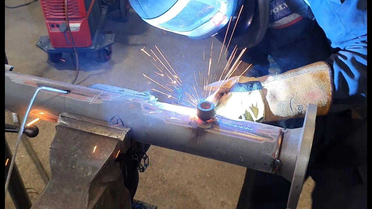
- Joint position: Decide whether the pipe will rotate or remain fixed; the practical settings and gun movement may change.
- Wall thickness: Thin tubing needs heat control to avoid burn-through, while thick pipe may require beveling, multiple passes, or preheat.
- Service requirements: A decorative or noncritical connection has different inspection needs from pressure, structural, fuel, or process piping.
- Process suitability: Confirm that a qualified procedure allows MIG for the material and service instead of assuming any pipe can be welded safely.
Pipe materials and joint types
Carbon steel is commonly welded with solid ER70S-series wire and a suitable argon-rich gas blend or carbon-dioxide-containing shielding gas. Stainless steel, aluminum, galvanized steel, and dissimilar metals need different wire, gas, cleaning methods, and sometimes specialized equipment.
A butt joint between two pipes usually requires more attention to root opening and alignment than a lap or fillet connection A square butt joint may work on.
Rotating pipe versus fixed pipe
When a positioner rotates the pipe, keep the weld pool in a comfortable working range instead of allowing it to run overhead. Rotation speed must match welding speed; too much rotation can produce a narrow, poorly fused bead, while too little can overheat one area.
For fixed pipe plan the weld in manageable segments Many welders use a sequence that limits heat concentration and allows each section to tie into the previous one.
Equipment, Wire, Gas, and Safety Preparation
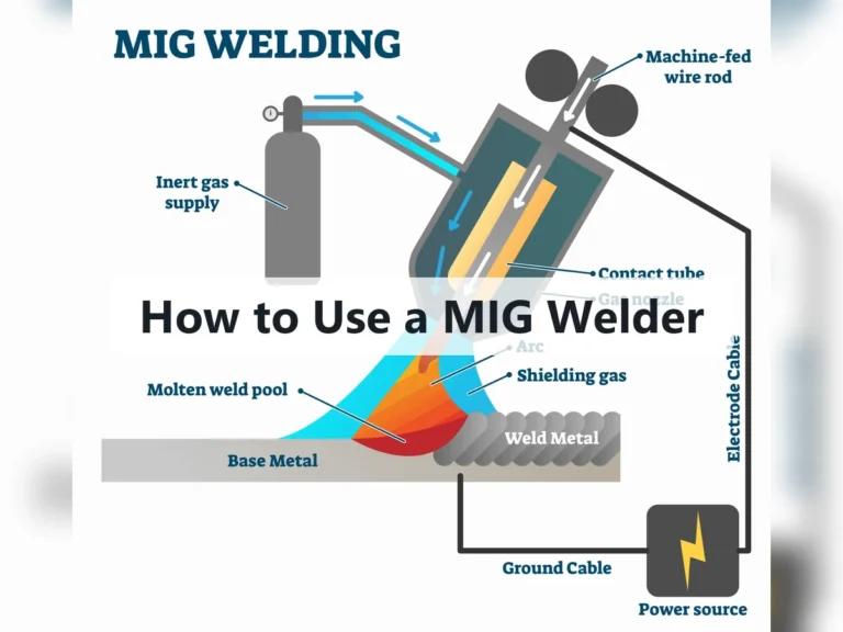
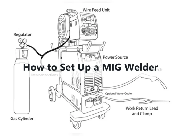
A reliable weld begins with equipment that can deliver a stable arc Use a MIG power source with enough output for the pipe thickness and duty cycle a.
Before welding, inspect the gun cable, ground lead, connections, gas hose, and cylinder. A loose ground or restricted liner can imitate a bad machine setting. Gas leaks and poor coverage can create porosity even when the voltage and wire-feed speed appear correct.
- Ventilation: Provide effective ventilation and avoid breathing welding fumes, especially when coatings, stainless alloys, or contaminated surfaces are involved.
- Fire control: Remove combustible materials and check the opposite side of the pipe for trapped liquids, vapors, insulation, or residues.
- Personal protection: Use the correct helmet shade, flame-resistant clothing, gloves, hearing protection, and safety footwear.
- Pipe isolation: Never weld a pipe or container that may be connected to a pressurized, energized, or hazardous system without proper isolation and authorization.
Choosing solid wire or flux-cored wire
Solid wire is a natural choice for shop and field MIG work where clean surfaces and shielding gas are available. It produces little slag and makes visual inspection easier. It is also sensitive to wind, drafts, dirty steel, and poor gas coverage.
Gas-shielded flux-cored wire can provide more tolerance in some outdoor or higher-deposition applications but it is still not immune to wind and requires removal of slag between passes.
Shielding gas and gas flow
Common solid-wire choices for mild steel include an argon-and-carbon-dioxide blend or carbon dioxide alone, depending on the desired transfer mode and equipment. Argon-rich mixtures generally support a smoother arc and lower spatter, while higher carbon dioxide content can increase penetration and spatter.
Use the gas type and flow range specified for the wire and application Excessive flow can create turbulence that pulls air into the shielding envelope so turning the.
Polarity, liner, and consumables
Most solid MIG wire applications use direct current electrode positive, but always verify the wire label and machine setup. Incorrect polarity can cause an unstable arc, excessive spatter, poor penetration, or an unusual bead profile.
Match the contact tip to the wire diameter and replace tips that are worn blocked or enlarged Keep the liner clean and avoid sharp bends in the gun.
How to MIG Weld Pipe: Preparation and Setup
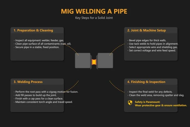
Before striking an arc, make the joint physically ready to weld. Remove oil, paint, rust, mill scale, moisture, and coatings from the weld area and adjacent surfaces. Cleaning should expose sound base metal without creating a sharp groove or contaminating the joint with unsuitable abrasives.
Align the pipes and check the circumference for mismatch. A small variation may be manageable, but excessive hi-low forces the arc to bridge uneven edges and can produce inconsistent penetration. Tack welds should hold alignment without becoming oversized obstacles that the final bead must flow around.
This distinction matters when answering “how to mig weld pipe”.
- Root opening: Use a consistent gap appropriate for the joint design, material thickness, and approved procedure.
- Bevel and land: On thicker pipe, maintain a uniform bevel and root face so penetration is predictable.
- Tack placement: Distribute tacks evenly and inspect them for cracks, porosity, or poor fusion before welding over them.
- Access: Confirm that the gun, nozzle, and your hand can reach the joint without forcing an unstable body position.
Starting machine settings
Set voltage, wire-feed speed, inductance, and related controls from the wire manufacturer’s data, the machine chart, or a qualified procedure. These are starting points, not guarantees, because actual results depend on stickout, joint geometry, position, gas, and surface condition.
Make a test weld on material of similar thickness before welding the actual pipe Listen for a consistent arc and examine the bead If the wire repeatedly pushes.
Gun angle, stickout, and travel direction
Keep the contact-tip-to-work distance consistent. A long stickout reduces effective current at the arc and can make penetration unpredictable; a very short stickout increases the risk of the tip touching the work and can destabilize the arc.
A modest work angle helps direct the arc into the joint Excessive drag or push angle can disturb shielding and change penetration For many joints a slight push.
Making the tack welds
Place tacks where they will not interfere with the root. Check that each tack is fused at both sides of the joint and that the pipe has not moved. If a tack is cracked, porous, or poorly bonded, remove the defective portion before continuing.
For larger pipe, use enough tacks to control alignment, but avoid making them so large that they become separate welds hidden under the final pass. Feather or blend the ends of sound tacks when needed so the next weld can tie in smoothly.
Running the Weld Around the Pipe
Once the joint is prepared begin with a controlled arc and a weld pool that is large enough to fuse both sides without spilling beyond the joint Watch.
For a rotating pipe, coordinate rotation with torch movement so the joint arrives in front of the arc at a steady rate. For fixed pipe, divide the circumference into sections and change body position before your hand becomes cramped or your view becomes obstructed.
- Watch both toes: The bead should wash into both sides of the joint rather than sit on top of one edge.
- Maintain rhythm: A steady travel speed is usually more valuable than a wide, decorative weave.
- Pause with purpose: Brief pauses at the sidewalls can improve tie-in, but excessive dwelling causes undercut, excess reinforcement, or burn-through.
- Clean between passes: Remove spatter, slag, and oxides before adding another pass.
Flat and horizontal portions
In the flat section the puddle is generally easiest to control Use this area to establish a consistent bead width and travel rhythm Avoid racing through the joint.
As the joint approaches the side, gravity begins to pull the puddle downward. Reduce puddle size and avoid excessive weaving. If the molten metal starts to sag, shorten the arc slightly if appropriate, increase travel speed carefully, or adjust settings according to the procedure.
Vertical portions
Vertical pipe welding demands close attention to heat input. A small side-to-side movement or controlled pause can help the arc reach both edges, but the movement should be narrow enough to keep the puddle from becoming heavy.
For uphill welding travel is typically slower and penetration can be strong but the puddle must remain small Downhill travel can be faster on suitable thin-wall applications yet.
Overhead portions
Overhead welding is the least forgiving position because gravity pulls molten metal away from the joint. Keep the puddle compact, maintain a steady arc, and avoid excessive wire deposition. A weave that works in flat welding may cause dripping or trapped defects overhead.
Plan your stance and gun support before starting. If your helmet, gloves, or body position forces you to lose sight of the joint, stop and reposition rather than trying to weld through a poor angle.
Single-Pass and Multi-Pass Pipe Welds
Thin-wall pipe may be completed in one pass when the joint design and service allow it The aim is complete fusion without excessive reinforcement or burn-through If the.
Multi-pass welding divides the required weld metal into a root pass, fill passes, and a cap pass. Each pass should be cleaned and inspected before the next. The cap should blend with the base metal without sharp undercut, excessive convexity, or an abrupt termination.
Keep these limitations in mind when considering “how to mig weld pipe”.
- Root pass: Establishes penetration and must tie into both sides of the joint without leaving an incomplete root.
- Fill passes: Build thickness while maintaining interpass cleanliness and controlling heat.
- Cap pass: Provides the final profile; it should not be used to hide an uncorrected root or fill defect.
Heat input and interpass temperature
Heat input is influenced by amperage voltage travel speed and process efficiency More heat can improve fusion but too much can enlarge the heat-affected zone distort the pipe.
On thick or restrained pipe preheat and interpass temperature may be required to reduce cracking risk and control cooling These requirements depend on alloy thickness restraint hydrogen control.
Common MIG Pipe Welding Mistakes and Fixes
Most defects have more than one possible cause. Diagnose the pattern, location, and appearance instead of changing several controls at once. Make one controlled adjustment, then test again on similar material.
- Welding over contamination: Oil, paint, moisture, rust, and coatings can cause porosity and inclusions.
- Inconsistent stickout: Changes in gun distance alter current, arc length, and deposition.
- Excessive travel speed: Can leave a narrow bead, poor sidewall fusion, or insufficient penetration.
- Excessive heat: Causes burn-through, undercut, distortion, and an oversized heat-affected area.
Porosity
Porosity appears as holes or gas pockets in the weld. Common causes include low or interrupted gas flow, wind, a leaking hose, a blocked nozzle, excessive stickout, contaminated base metal, or moisture. Spatter inside the nozzle can disrupt the shielding pattern.
Check the cylinder, regulator, hose, connections, nozzle, and work area. Clean the metal and use a suitable flow rate. If porosity is found in a critical weld, do not simply cover it with another bead; remove and repair it according to the applicable procedure.
Lack of fusion and incomplete penetration
Lack of fusion occurs when the weld metal does not bond properly to the sidewall or previous pass It may result from low heat excessive travel speed an.
Improve joint preparation, direct the arc toward the unfused edge, and adjust voltage, wire-feed speed, travel speed, or technique within approved limits. A bead that sits high and rounded on the joint is a warning sign, not proof of penetration.
Burn-through and excessive penetration
Burn-through is common on thin pipe wide root gaps and areas where the operator pauses too long Reduce heat input only as far as fusion remains adequate Faster.
Do not compensate for a poor fit-up by dramatically reducing heat. A consistent root opening and proper alignment usually provide a better solution than trying to weld around an oversized gap.
Undercut, overlap, and poor profile
Undercut is a groove melted into the base metal beside the weld that remains unfilled. It can come from excessive voltage, excessive travel speed, a long arc, too much weaving, or lingering at the center instead of filling the toes.
Overlap occurs when weld metal rolls onto the base metal without fusing. A smaller puddle, correct travel speed, better angle, and adequate heat can improve tie-in. Grind or remove unacceptable defects before repair welding; do not assume a cosmetic cap will make them harmless.
Inspection, Repair, and Quality Decisions
Inspect the joint after it has cooled enough to handle safely Look for a continuous bead smooth transitions sound tie-ins at starts and stops and the absence of.
Visual inspection cannot prove internal soundness Depending on the application inspection may include liquid penetrant magnetic-particle radiographic ultrasonic dimensional or pressure testing performed under the appropriate procedure Pressure testing is not a substitute for correct welding and should.
- Starts and stops: Confirm that the bead begins and ends without craters or unfilled tie-ins.
- Root condition: Verify penetration using the permitted inspection method, not appearance alone.
- Profile: Check reinforcement, width, undercut, overlap, and abrupt transitions.
- Repair plan: Remove defects to sound metal, clean the excavation, and follow the repair procedure.
When a weld should be rejected
Reject or hold a weld when there is visible cracking, significant porosity, incomplete fusion, unacceptable undercut, severe distortion, or any condition outside the governing acceptance criteria. A strong-looking bead can still fail if the root is defective or the pipe wall was damaged by excessive heat.
For noncritical hobby work, the owner may decide that a minor cosmetic imperfection is acceptable. That decision does not transfer to pressure, structural, fuel, medical, or other regulated systems, where qualified procedures and competent inspection are essential.
FAQ: How to MIG Weld Pipe
Can you MIG weld all types of pipe?
No. MIG can be suitable for many carbon-steel and some stainless or aluminum pipe applications, but the wire, gas, polarity, preparation, and procedure must match the material and service.
Pipe connected to pressure, fuel, hazardous, or structural systems may require a qualified process other than MIG or additional qualification and inspection. Confirm the requirements before welding.
What wire size is best for MIG welding pipe?
Wire size depends mainly on pipe thickness, welding position, machine capacity, joint design, and required deposition rate. Smaller wire is often easier to control on thin-wall pipe, while larger wire can support higher deposition on thicker material.
Use the machine chart, wire data, and procedure as the starting point. Do not choose wire only because it is already installed in the welder.
Should I push or pull the MIG gun on pipe?
A slight push or drag angle may work depending on the wire type, position, joint, and desired penetration. Solid wire is commonly used with a modest push angle for visibility and a broad arc, while some flux-cored applications favor dragging.
The essential goal is a stable arc, adequate shielding, and fusion at both sides of the joint. Excessive angle is more harmful than the small difference between a controlled push and drag.
Can I MIG weld pipe outdoors?
You can use MIG outdoors only when shielding gas can be protected from wind and the wire, gas, and procedure are appropriate. Even a moderate draft can disperse the gas and create porosity.
Use suitable wind protection, inspect the gas system, and test the weld. If conditions cannot be controlled, a self-shielded flux-cored process may be more appropriate, but it requires different settings and technique.
Why does my pipe weld look good but fail?
Appearance does not reveal every internal defect. A bead may be smooth while containing lack of fusion, incomplete penetration, slag inclusions, or porosity beneath the surface.
Possible causes include incorrect fit-up, low heat, excessive travel speed, poor joint access, contaminated metal, or unsuitable settings. Use the inspection method required for the application instead of relying only on visual appearance.
How do I prevent burn-through on thin pipe?
Start with a consistent, properly sized root gap and clean, well-aligned edges. Use a wire and heat range suited to the wall thickness, keep the puddle small, maintain steady travel, and avoid long pauses.
Test on scrap of the same material and position before welding the actual joint. If the pipe is too thin or the joint is poorly supported, another process or joint design may offer better control.
Is MIG welding pipe suitable for pressure piping?
It may be suitable in some applications, but not by default. Pressure piping normally requires an approved welding procedure, qualified personnel, specified materials, inspection, and acceptance criteria.
Do not rely on general shop settings for a pressure boundary. Follow the applicable engineering and safety requirements before beginning work.
Conclusion
Successful pipe welding depends on the entire sequence compatible materials clean preparation accurate fit-up stable equipment controlled settings and technique that adapts to the pipe position When learning.
MIG is efficient and versatile, but it has limits in wind, difficult positions, contaminated surfaces, very thin walls, and critical service applications. Use the correct procedure and inspection standard, and stop when the joint or surrounding system presents a safety risk.
Practice on matching pipe, record the settings that produce sound fusion, and inspect a test joint before welding the final assembly.
The answer to “how to mig weld pipe” should be applied with these conditions and limitations in mind.