How to Set Up a MIG Welder for Aluminum: Detailed Guide and Facts
Use a spool or push-pull gun, aluminum wire, 100% argon, DCEP polarity, a U-groove drive roll, and settings matched to the material thickness.
How to set up a MIG welder for aluminum depends on more than voltage and wire speed The wire diameter welding gun shielding gas joint design machine output.
Imagine you need to repair a cracked aluminum trailer component with a conventional MIG machine will the machine gun wire-feeding system and settings work together or will a.
This guide explains the equipment choices polarity gas flow wire-feeding adjustments surface preparation starting settings and welding technique that produce the most dependable results You will also learn.
- ✓Use a dedicated aluminum wire path whenever possible because soft wire feeds poorly through long steel liners.
- ✓Set the machine to DCEP and use pure argon shielding gas, not an argon-carbon dioxide steel mixture.
- ✓Clean aluminum immediately before welding with a dedicated stainless-steel brush and remove oil or moisture first.
- ✓Begin with the machine manufacturer’s aluminum chart, then fine-tune voltage, wire speed, travel speed, and gun angle.
How to Set Up a MIG Welder for Aluminum?
Aluminum wire is softer and more easily damaged than solid steel wire. That difference affects the entire feeding system, especially when the wire must travel through a long conduit from the machine to a conventional MIG gun.
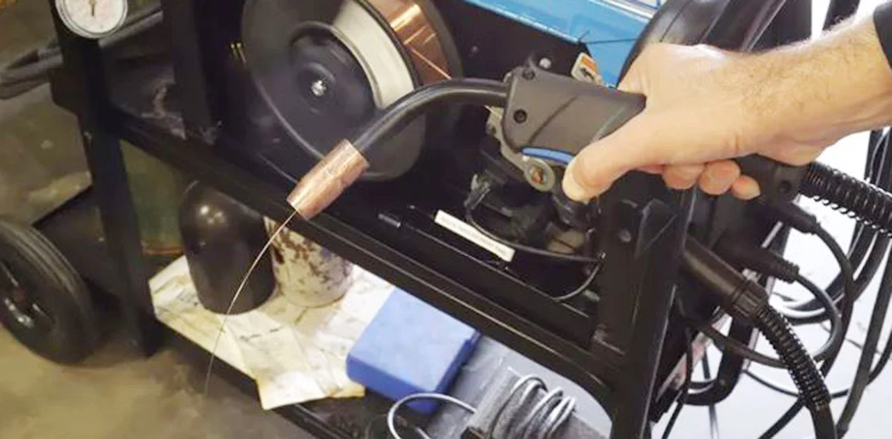
For occasional repairs a spool gun is usually the simplest solution It places a small spool of aluminum wire at the gun reducing the distance the soft wire.
- Gun type: Choose a spool gun or push-pull system designed and electrically compatible with the welder.
- Wire diameter: Common aluminum choices include 0.030, 0.035, and 0.047 inch, depending on the machine and workpiece.
- Drive roll: Use a U-groove roll sized for aluminum wire; a sharp V-groove can deform it.
- Contact tip: Select a tip made for the wire diameter, often with slightly more clearance than a steel-wire tip.
When a spool gun is the better choice
A spool gun is appropriate when the welder supports one and the job uses a modest amount of.
The trade-off is weight and access A spool gun can feel bulky in tight corners and the small spool may require more frequent replacement during larger projects It.
When a push-pull gun makes sense
A push-pull system is useful for production work, long-reach welding, or situations requiring a larger spool. The feeder pushes the wire while the motor in the gun pulls it, keeping the wire under controlled tension.
Push-pull equipment must be matched to the welder and correctly configured. If the gun motor, feeder, drive rolls, or control connection are incompatible, feeding may be erratic even when the machine’s electrical settings are correct.
Choose the aluminum wire before setting the machine
ER4043 is a common general-purpose filler with good fluidity and a relatively low melting range. It is often selected for many cast and wrought aluminum repairs, although it is not the best choice for every base alloy or service condition.
ER5356 generally offers higher strength and better suitability for some aluminum-magnesium base metals. It can require different handling and may be preferred where anodizing appearance, strength, or service conditions influence the filler choice.
Do not choose filler metal only by convenience The base alloy required strength exposure to chemicals or salt water appearance and post-weld use can all matter For structural.
Prepare the Welder, Polarity, Wire, and Shielding Gas
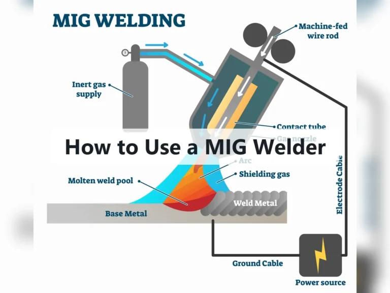
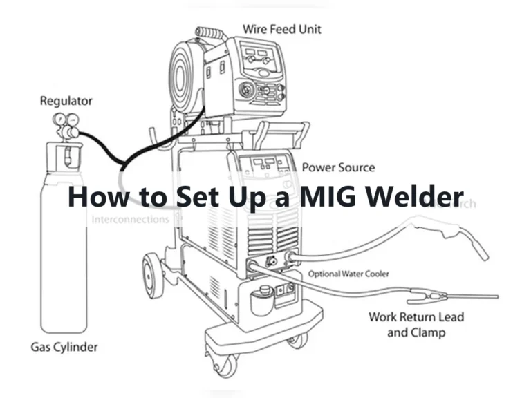
Before changing machine settings turn off the welder and confirm that the gun feeder and spool are compatible Aluminum MIG welding normally uses direct current electrode positive commonly.
Use 100% argon for most aluminum MIG work. Gas intended for mild steel, such as an argon-carbon dioxide blend, can create excessive spatter, unstable shielding, and poor weld quality on aluminum.
- Polarity: Connect the gun lead to positive and the work lead to negative unless the machine or wire manufacturer specifies otherwise.
- Gas: Use clean welding-grade argon with a regulator and flowmeter suitable for the cylinder.
- Connections: Check the ground clamp, gun connection, gas hose, and spool-gun control plug before striking an arc.
- Ventilation: Keep the area ventilated and prevent fans or drafts from blowing shielding gas away from the arc.
Install the spool without crushing the wire
Mount the spool so the wire pays off in the direction specified by the feeder Set the spool brake just tight enough to prevent overrun when the trigger.
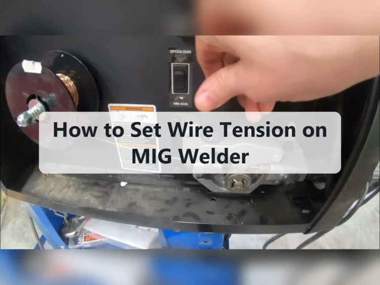
Feed the wire through the correct inlet guide and U-groove drive roll. Tighten the drive-roll pressure gradually. The goal is enough pressure to move the wire without slipping, not enough pressure to flatten or mark it.
Use the correct liner and contact tip
A conventional steel liner can add friction and leave contamination on aluminum wire. A low-friction liner designed for aluminum, or a spool gun with a very short path, improves feeding reliability.
Install a contact tip matched to the wire diameter Aluminum expands as it heats so a tip that is excessively tight can cause the wire to bind If.
Set shielding gas flow sensibly
Begin with the flow rate recommended by the gun and machine manufacturer. A moderate argon flow is commonly used, but the correct value depends on nozzle size, welding position, indoor airflow, and the distance between the nozzle and workpiece.
More gas is not always better Excessive flow can create turbulence that pulls surrounding air into the shielding zone If the weld develops gray or black contamination first.
Clean and Fit the Aluminum Before Welding
Aluminum forms a tough oxide layer almost immediately. The oxide melts at a much higher temperature than the base aluminum, so an apparently clean surface can still interfere with wetting and fusion.
Remove oil grease marker residue adhesive and other contamination with a suitable solvent and clean lint-free material After the solvent has evaporated use a dedicated stainless-steel brush to. This distinction matters when answering “how to set up a mig welder for aluminum”.
- Degrease first: Brushing before removing oil can spread contamination across the joint.
- Brush direction: Use firm, controlled strokes over the joint and adjacent surfaces.
- Fit-up: Remove excessive gaps and align the parts because aluminum can melt away quickly.
- Moisture: Keep the work dry; damp contamination can contribute to porosity and unsafe arc conditions.
Control the joint gap and edge condition
Aluminum transfers heat quickly, but its low melting temperature means thin edges can collapse before the surrounding metal becomes evenly heated. A large gap increases the amount of filler needed and makes burn-through more likely.
Use a tight consistent fit-up when possible On thicker material beveling may be necessary to achieve the required penetration A sharp outside corner can be especially vulnerable to.
Understand heat buildup
Aluminum often feels manageable at the beginning of a weld and then suddenly becomes too hot As the part warms the puddle becomes more fluid and the risk.
Use short welds staggered sequences clamps heat sinks or pauses when appropriate Do not quench a hot weld with water as a routine shortcut rapid cooling can.
Choose Starting Settings for Aluminum MIG Welding
There is no universal voltage and wire-speed combination for aluminum. Machine design, transfer mode, wire diameter, alloy, thickness, joint position, and spool-gun cable characteristics all affect the result. The welder’s aluminum chart or manual should be the first reference.
Many machines use a synergic program that links voltage and wire speed. Others require separate adjustment. In either case, make a test weld on scrap aluminum that matches the production material as closely as possible.
- Start with the chart: Select the wire alloy, diameter, material thickness, and transfer mode if available.
- Watch the arc: A smooth, consistent arc is more useful than copying a number from an unrelated machine.
- Adjust one control: Change voltage, wire speed, or travel technique separately so the cause of improvement is clear.
- Test position: A flat-position test does not fully predict behavior on vertical or overhead joints.
Voltage and wire speed
Voltage influences arc length and bead shape while wire speed largely controls deposition rate and in many machines amperage The controls interact Increasing wire speed without an appropriate.
If the arc sounds erratic and the wire appears to stub into the work wire speed may be too high for the selected voltage or the contact tip.
Wire diameter and material thickness
Smaller wire can help with thin aluminum because it permits lower deposition and more precise control Larger wire.
Do not assume a larger wire automatically produces deeper penetration. Penetration depends on heat input, joint design, travel speed, arc characteristics, and technique. Use the smallest practical wire that the machine and application support, then verify fusion on test pieces.
Inductance, arc control, and pulse settings
Some advanced machines provide inductance, arc-control, or pulse adjustments. These controls change the character of the arc and can help manage heat, spatter, and puddle fluidity, but their labels and useful ranges vary widely by machine.
If the machine offers a dedicated aluminum or pulse program begin there rather than building a setting from a steel program Pulse can reduce average heat input and.
Set Gun Position, Stickout, and Travel Technique
Aluminum MIG welding usually benefits from a slight push angle rather than dragging the gun. Pushing helps place shielding gas ahead of the puddle and can produce a cleaner bead. Keep the gun angle consistent and avoid excessive side-to-side movement.
Maintain the stickout recommended by the machine or gun instructions. Excessive stickout increases electrical resistance outside the contact tip, heats the wire prematurely, and reduces arc control. Too little stickout can make the tip overheat or contact the puddle.
- Push angle: Use a modest forward angle and keep the nozzle close enough for reliable coverage.
- Travel speed: Move steadily; hesitating in one area can quickly cause burn-through.
- Puddle control: Watch the leading edge of the puddle rather than only the finished bead.
- Starts and stops: Restart on clean metal or overlap carefully to avoid craters and cold starts.
Why aluminum often needs a faster hand
Once aluminum reaches welding temperature, it can lose strength and collapse quickly. A deliberate but reasonably fast travel speed helps limit heat buildup, especially on thin sheet.
Travel too fast however can leave insufficient fusion or a narrow bead that does not tie into both sides of the joint The correct speed is the one.
Use the correct bead pattern
A straight bead is often preferable for thin material and sound fit-up. Excessive weaving increases heat input and can trap contamination or gas in the weld. If a wider bead is necessary, use only enough motion to cover the joint.
For thicker sections, multiple controlled passes may be better than one oversized pass. Clean between passes, inspect the profile, and avoid burying visible contamination under additional metal.
Recognize and Correct Common Aluminum MIG Problems
Most aluminum MIG defects have a small group of likely causes: contaminated material, poor shielding, unstable wire feeding, incorrect polarity, unsuitable settings, or inconsistent technique. Diagnose the system rather than changing several variables at once. Keep these limitations in mind when considering “how to set up a mig welder for aluminum”.
Make a short test weld, note the arc sound and puddle behavior, and inspect both the bead and the opposite side of the joint when possible. A shiny surface alone does not prove adequate fusion.
- Bird-nesting: Reduce feeding resistance, check liner alignment, use the correct drive roll, and avoid excessive drive pressure.
- Porosity: Check cleaning, gas flow, leaks, drafts, nozzle blockage, and moisture.
- Burn-through: Reduce heat input, increase travel speed, improve fit-up, or use shorter welds.
- Poor fusion: Check joint preparation, travel speed, arc placement, and whether the machine has enough output.
Bird-nesting and wire feeding jams
Bird-nesting occurs when soft wire buckles near the drive rolls or inlet guide. Common causes include too much drive-roll pressure, a blocked liner, excessive friction, a misaligned spool, or a gun cable bent sharply.
Cut away the tangled wire and inspect the path from the spool to the contact tip Replace damaged liner components use the proper aluminum drive roll and set.
Porosity, soot, and dirty-looking welds
Porosity may result from inadequate shielding or hydrogen-related contamination from oil, water, or dirty surfaces. Inspect the gas hose and fittings for leaks, confirm the cylinder contains argon, and keep the nozzle free of spatter.
Black soot around an aluminum weld can indicate poor shielding excessive arc length insufficient cleaning or an unfavorable.
Burn-through and excessive melt-away
Burn-through is especially common on thin aluminum, at unsupported edges, and near the end of a long weld. Reduce the heat input through the machine settings and travel technique, but do not simply move so quickly that the joint lacks fusion.
Use intermittent welds or skip sequences when the application permits. A copper backing bar can support the puddle and draw away heat, provided it fits tightly and does not create an unintended defect or restrict access.
Cracking and weak joints
Cracking can be related to filler selection, joint restraint, contamination, crater shape, or an unsuitable welding procedure. Avoid abruptly stopping and leaving a deep crater. Fill the crater appropriately or use a controlled termination method supported by the machine.
If a repaired component carries a load, experiences vibration, or affects vehicle or equipment safety, do not rely on visual appearance alone. The alloy, filler, heat treatment, and service requirements may demand qualified procedure control and inspection.
Safety and Quality Checks Before the Final Weld
Aluminum MIG welding produces intense ultraviolet radiation, hot metal, fumes, and sparks. Wear a properly rated welding helmet, flame-resistant clothing, gloves, and appropriate footwear. Remove flammable materials from the area and protect nearby people from arc flash.
Use ventilation that removes fumes without creating a cross-draft at the weld Do not weld containers tanks or enclosed spaces unless they have been properly cleaned isolated and.
- Gas cylinder: Secure the argon cylinder upright and protect the valve from impact.
- Electrical safety: Keep cables, gloves, and work surfaces dry and inspect damaged leads before use.
- Hot work: Mark or isolate hot aluminum because it can be difficult to judge temperature by appearance.
- Inspection: Stop if the machine, gun, regulator, or cable overheats or behaves abnormally.
Inspect the test weld
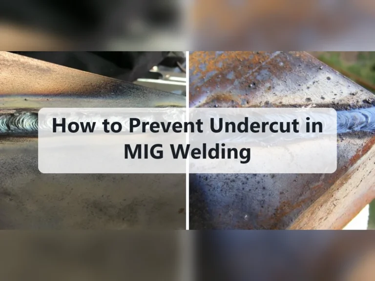
Look for a consistent bead profile smooth tie-in at both toes minimal soot and no visible pinholes or cracks Check the back of the joint when access permits.
A weld can look attractive while lacking fusion beneath the surface. Confirm that the settings and procedure are appropriate for the actual base material, thickness, position, and service requirements rather than judging only by color or shine.
Know when MIG is not the best process
MIG is efficient for many aluminum fabrication and repair tasks, particularly when deposition speed matters. TIG can offer finer control for thin sheet, visible work, intricate joints, and applications where precise heat management is more important than speed.
Very thick aluminum, heat-treated alloys, castings with unknown composition, and safety-critical components may require specialized procedures. If you cannot identify the alloy or evaluate the consequences of failure, obtaining qualified welding assistance is the safer decision.
Maintenance After Aluminum MIG Welding
Aluminum wire leaves softer residue and can expose feeding problems that remain hidden with steel wire After welding.
Store aluminum wire in a clean dry environment Contaminated or damp wire can contribute to feeding problems and.
- Consumables: Remove spatter and replace a damaged nozzle, tip, or liner.
- Drive system: Clean the groove and confirm that the roll still grips without crushing wire.
- Gas system: Close the cylinder valve when finished and inspect connections for leaks.
- Wire end: Secure the spool so the wire cannot unwind or collect dirt.
FAQ: Setting Up a MIG Welder for Aluminum
Can any MIG welder weld aluminum?
No. The welder must have suitable output, compatible controls, the correct polarity connection, and a wire-feeding solution for soft aluminum wire. A machine that only accepts a standard steel gun may need a compatible spool gun or push-pull upgrade.
What gas should be used for aluminum MIG welding?
Use 100% argon for most aluminum MIG applications. Avoid ordinary steel shielding-gas mixtures containing carbon dioxide unless a specific welding procedure and equipment manufacturer expressly supports that gas for the application.
Should aluminum MIG welding use straight or reverse polarity?
Typical aluminum MIG welding uses DCEP, also called reverse polarity. Confirm the lead arrangement in the welder manual because the machine’s terminals and polarity-selection method can differ.
Why does aluminum wire keep jamming in the gun?
Soft wire commonly jams because of excessive drive-roll pressure, a sharp V-groove, a dirty or high-friction liner, a tight gun cable, a worn contact tip, or misaligned guides. A spool gun usually solves the long-feed problem by shortening the wire path.
Can I use the same MIG settings for steel and aluminum?
No. Aluminum normally requires different wire, shielding gas, polarity, feeding hardware, and electrical settings. Start with the aluminum program or chart rather than adapting a steel setting by guesswork.
How do I prevent aluminum MIG welds from becoming porous?
Degrease the joint, brush the oxide with a dedicated stainless-steel brush, use clean argon, check for gas leaks and drafts, and keep the nozzle and contact tip in good condition. Also avoid welding damp or contaminated material.
Is preheating aluminum necessary before MIG welding?
Preheating is not automatically required and can be harmful if it overheats the material or masks poor technique. For thick sections, controlled preheating may help manage heat flow, but use the temperature and procedure appropriate for the alloy and application.
Conclusion
Learning how to set up a MIG welder for aluminum means coordinating the wire-feeding system aluminum filler DCEP polarity pure argon consumables surface preparation and machine settings Begin.
The major limitation is that generic settings cannot replace an application-specific procedure, especially for structural, pressure, vehicle-safety, or heat-treated aluminum. Use proper protective equipment, ventilation, and qualified help when the consequences of a failed weld are serious.
Install the correct aluminum consumables, clean a scrap coupon thoroughly, and make a short DCEP test weld before working on the final part.