How to Set Up a MIG Welder: Setup Steps and Troubleshooting Tips
To set up a MIG welder, install the correct wire and contact tip, connect shielding gas if required, set polarity, adjust voltage and wire speed, then test on scrap metal.
Learning how to set up a mig welder correctly saves wire prevents weak joints and reduces the risk of burns arc flash gas leaks and electrical problems The.
One-size-fits-all advice is the main reason new welders struggle A setting that produces a smooth bead on 1 8-inch mild steel may burn through thin sheet metal or.
This guide explains the equipment checks, spool and gun setup, polarity, shielding gas choices, starting settings, and safe testing process. It also covers the most common causes of porosity, spatter, burn-through, poor penetration, wire feeding problems, and unstable arcs so you can adjust with a reason instead of guessing.
- ✓Match wire, gas, polarity, contact tip, and settings to the material and welding process.
- ✓Use the machine’s chart as a starting point, then fine-tune on clean scrap of the same thickness.
- ✓Keep the gun at the correct distance and angle while maintaining a steady travel speed.
- ✓Stop immediately for gas leaks, damaged cables, exposed conductors, fumes, or unsafe work conditions.
How to Set Up a MIG Welder Before
Before changing controls, identify what you are actually welding. Most beginner MIG work involves solid ER70S-type mild-steel wire with an argon-and-carbon-dioxide shielding blend, but aluminum, stainless steel, and flux-cored wire require different choices. Read the welder’s front-panel instructions and the wire manufacturer’s label because equipment ranges and recommended settings vary.
Prepare a stable dry work area with good ventilation and a fire-resistant surface Remove flammable materials secure the workpiece and make sure the welder has the correct input.
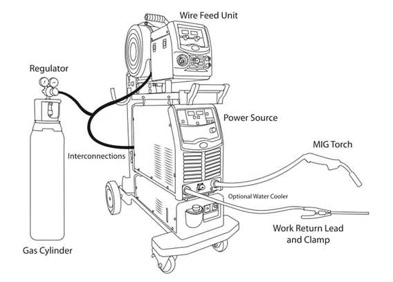
- Material: Confirm the metal type, thickness, coating, and cleanliness before choosing wire or gas.
- Machine capacity: Verify that the welder’s output and duty cycle suit the job and available electrical supply.
- Work area: Remove combustibles, provide ventilation, and keep a suitable fire extinguisher accessible.
- Personal protection: Inspect the helmet lens, gloves, jacket, and footwear before welding.
Identify the wire and welding process
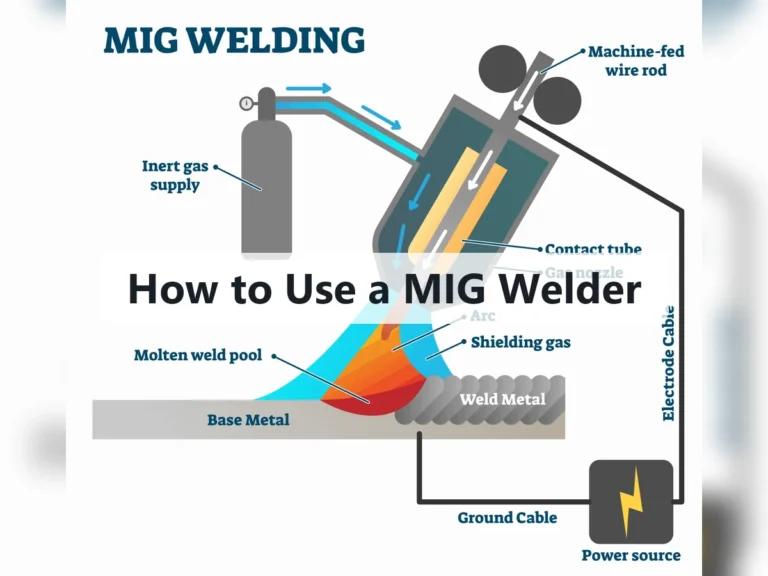
Solid wire requires external shielding gas and normally creates a clean low-slag bead It is a common choice for indoor mild-steel work Flux-cored wire may be self-shielded or.
Do not assume that every flux-cored spool uses the same polarity. Some self-shielded wires run electrode negative, while gas-shielded wires and many solid-wire MIG setups run electrode positive. The wire label and machine instructions take priority over a general rule.
Clean and prepare the joint
Paint, rust, oil, mill scale, moisture, and galvanizing can contaminate the weld or release hazardous fumes. Clean the joint and the area where the work clamp will attach. A grinder or wire brush can remove surface contamination, but avoid spreading oily residue across the metal.
When welding coated or painted material, remove the coating well beyond the weld zone and use suitable ventilation. Welding galvanized steel is especially hazardous because zinc fumes can cause serious illness; avoid welding it unless the coating can be safely removed and the work area is properly controlled.
Install the Wire, Gun, Contact Tip, and Shielding Gas
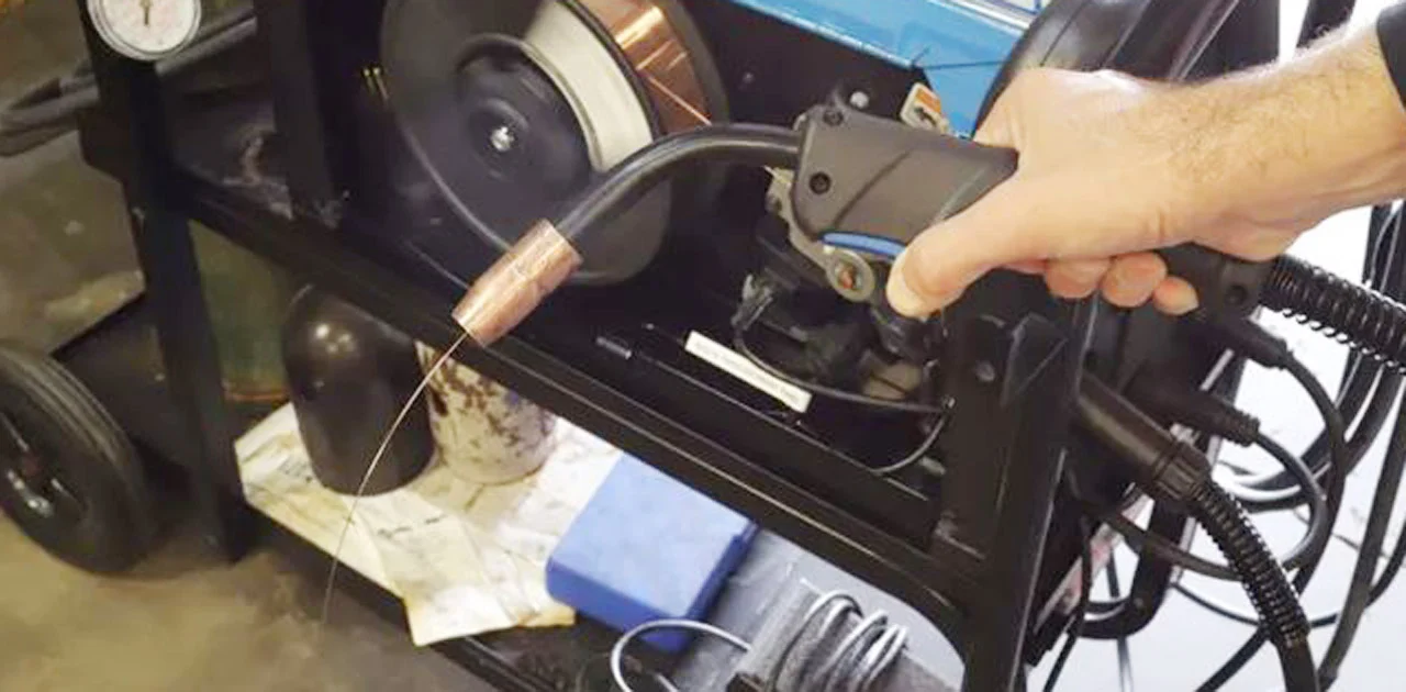
Turn the welder off before installing a spool, changing the drive-roll pressure, or replacing a contact tip. The wire path must be smooth from the spool to the gun liner. Excessive tension can deform soft wire, while insufficient tension allows the drive rolls to slip and creates inconsistent feeding.
Choose a spool and contact tip that match the wire diameter Common steel wire sizes include 0 023 0 030 and 0 035 inch but the correct choice.
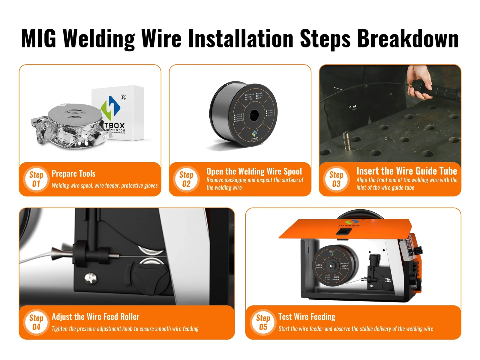
- Spool orientation: Install the spool so the wire unwinds in the direction shown by the machine, and keep the retaining nut snug.
- Drive rolls: Use the correct groove and set pressure only high enough to feed consistently.
- Contact tip: Match its size to the wire; a loose or worn tip can cause an erratic arc.
- Gun liner: Keep the liner clean and properly seated so the wire does not bind.
Thread the wire safely
Cut the bent end from the wire and hold the spool securely while releasing the retaining mechanism. Feed the wire through the inlet guide, drive rolls, and outlet guide. Close the drive-roll arm, but do not crush the wire with excessive pressure.
Remove the contact tip before feeding wire through the gun This reduces resistance and helps prevent a bird s nest if the wire encounters a blockage Keep the.
Set drive-roll tension without guessing
A practical check is to reduce tension hold the gun in a safe direction and gradually increase pressure until the wire feeds without slipping Then briefly hold the.
If the wire slips during normal welding, inspect the groove, liner, contact tip, and spool brake before simply tightening the tension. A worn groove, kinked liner, or overly tight spool brake can create the same symptom and may be made worse by more pressure.
Connect the shielding gas
For gas-shielded welding, secure the cylinder upright with a chain or strap. Check that the valve, regulator, hose, and fittings are rated for the gas being used. Open the cylinder valve slowly and check the regulator and hose connections for leaks using an approved leak-check method; never use a flame.
Set gas flow according to the machine or gas supplier’s guidance. Too little flow allows air into the weld pool, while excessive flow can create turbulence that draws air into the shielding area. Keep the hose away from sharp edges and hot metal, and protect the cylinder from impact or heat.
Choose Polarity, Gas, and Starting Settings
Polarity determines the direction of current through the welding circuit and strongly affects arc behavior and penetration. For many solid-wire steel MIG setups, the gun is connected to positive polarity and the work lead to negative polarity. That arrangement is not universal, so verify the wire specification before welding.
This distinction matters when answering “how to set up a mig welder”.
Shielding gas also changes arc characteristics A common argon-and-carbon-dioxide blend provides a relatively smooth arc for mild steel while straight carbon dioxide can offer deeper penetration at the.
- Solid wire: Uses shielding gas, creates no slag, and is often convenient for clean indoor steel work.
- Self-shielded flux core: Uses no external gas, tolerates some outdoor airflow better, and leaves slag to remove.
- Gas-shielded flux core: Requires the specified gas and polarity but can provide high deposition on suitable equipment.
- Aluminum: Usually needs an appropriate spool gun or wire-feeding system and an argon-based gas.
Use the machine chart as a starting point
Set the wire diameter material type and thickness on the welder if it has a programmed or synergic mode On a manual machine use the wire manufacturer s.
Voltage primarily influences arc length and bead profile, while wire-feed speed largely controls amperage and deposition rate. Increasing wire speed without an appropriate voltage change can make the wire stub into the work. Increasing voltage too far can make the arc long, harsh, and prone to undercut or excessive spatter.
Set inductance, burn-back, and other controls when available
Some welders include inductance arc control crater fill or burn-back settings Inductance changes how quickly current rises and falls affecting arc softness and spatter Burn-back controls how far.
Leave advanced controls near the manufacturer’s suggested starting point until the basic settings and technique are correct. A poor ground, contaminated metal, incorrect polarity, or excessive stick-out cannot usually be fixed with an advanced dial.
Make a Test Weld and Fine-Tune the Arc
A test weld is not wasted material it is the quickest way to confirm that the machine wire gas polarity and technique are working together Use a clean.
Set the gun at approximately a right angle to the joint then use a modest work angle that directs the arc into both pieces Maintain a consistent contact-tip-to-work.
- Arc sound: Look for a consistent, controlled arc rather than repeated popping, stubbing, or roaring.
- Bead shape: Check that the bead ties into both sides without excessive height, undercut, or craters.
- Fusion: Confirm that the weld has joined the base metal instead of sitting on top like a rope.
- Shielding: Watch for porosity, unusual discoloration, drafts, or a damaged nozzle.
- Place the gun at the start of the joint and position your body so the travel path is comfortable.
- Trigger the arc and begin moving at a steady speed. Do not stare at the bright arc without a properly rated helmet.
- Watch the leading edge of the weld pool, where the arc melts the base metal and filler wire.
- Release the trigger at the end of the weld and allow the post-flow, if present, to protect the hot area.
- Inspect the bead after it cools. Remove slag from flux-cored welds before judging the underlying weld.
Adjust one variable at a time
If the wire repeatedly hits the work and pushes the gun away wire-feed speed may be too high for the selected voltage or the wire may be feeding.
Make a small adjustment weld another short sample and compare the results Changing voltage wire speed gas flow travel speed and gun angle all at once makes it.
Travel angle and speed matter as much as the dial
A slight push angle is often used with gas-shielded solid wire, while flux-cored procedures may call for a drag angle depending on the wire. Follow the wire instructions when available. Excessive angle can pull shielding away from the pool or place too much heat on one side of the joint.
Travel too slowly and the bead becomes wide, tall, and excessively hot. Travel too quickly and the weld may be narrow, convex, and poorly fused. A steady hand, consistent stick-out, and a visible leading edge are more valuable than trying to weld as fast as possible.
Troubleshoot Common MIG Welding Problems
Most MIG defects come from a small group of causes: incorrect settings, poor preparation, unstable wire feeding, inadequate shielding, bad grounding, or inconsistent technique. Start with the simplest checks before replacing parts. Turn the machine off when inspecting the wire path or electrical connections.
Use the appearance of the bead and the sound of the arc as clues not as the only proof of quality A weld can look attractive while lacking fusion especially when the settings are too cold or the joint is.
- Changing too much: Adjusting several controls at once hides the real cause of a defect.
- Ignoring the ground: A loose or dirty work clamp can imitate a machine or wire problem.
- Welding through contamination: Oil, paint, rust, and moisture can create porosity and weak fusion.
- Using excessive gas: More flow is not automatically better and can introduce turbulence.
Porosity, pinholes, or a bubbly bead
Porosity usually indicates that atmospheric gas entered the molten weld pool. Check the cylinder level, regulator, hose, fittings, solenoid operation, and gas flow. Inspect the nozzle for spatter blockage and make sure wind, fans, or compressed-air movement are not disturbing the shielding.
Clean the base metal and maintain proper stick-out. If the problem appears only at the beginning or end of the weld, review pre-flow and post-flow settings and avoid moving the gun away before the pool has solidified. Keep these limitations in mind when considering “how to set up a mig welder”.
Excessive spatter or an unstable arc
Spatter can result from mismatched voltage and wire speed, incorrect polarity, contaminated metal, a poor ground, excessive stick-out, or unsuitable gas. Start by confirming polarity and wire type, then check the contact tip and drive rolls.
If the wire stubs into the plate, increase voltage slightly or reduce wire speed in small increments. If the arc becomes long and aggressive, reverse that approach. Make sure the wire is not binding in the liner, because intermittent feeding causes repeated arc-length changes.
Burn-through, lack of fusion, and a tall bead
Burn-through occurs when the heat input is too high for the material or the travel speed is too slow Reduce voltage or wire speed move more quickly shorten.
A tall bead, cold lap, or poor sidewall fusion can indicate insufficient heat, excessive travel speed, an incorrect gun angle, or an improperly prepared joint. Increase heat cautiously and direct the arc toward both sides of the joint. A wide gap may also require a different joint design or multiple passes.
Wire bird’s nests, burn-back, and feeding failures
A bird’s nest forms when wire stops moving beyond the drive rolls but the motor continues pushing it. Release the trigger immediately, turn off the machine, cut away the tangled wire, and inspect the liner, inlet guide, contact tip, drive-roll groove, and spool brake.
Burn-back leaves the wire fused to the contact tip. Common causes include feeding that is too slow, excessive burn-back time, a worn tip, or holding the gun too close to the work. Replace damaged consumables and correct the underlying feeding or control problem instead of repeatedly pulling on the wire.
Weak or inconsistent welds
Check the work clamp, cable connections, polarity, wire type, and material cleanliness. Confirm that the actual thickness is within the machine’s capacity and that the duty cycle has not been exceeded. If the machine repeatedly shuts down, allow it to cool and investigate airflow or overload conditions.
Do not rely on higher settings to compensate for a joint that has poor fit-up or excessive gaps. Proper alignment, adequate tack welds, and a controlled travel path often improve results more than simply increasing power.
Safety, Shutdown, and Routine Maintenance
Safe setup continues after the weld is complete. Hot workpieces can remain dangerous long after the arc stops, and sparks can travel farther than expected. Mark or isolate hot metal, keep gloves on when handling it, and inspect the surrounding area for smoldering material before leaving.
Ventilation should remove fumes from the breathing zone without creating a strong cross-draft over the arc. A respirator, when appropriate, is not a substitute for source control, clean metal, and adequate ventilation. Never weld in a container, tank, or confined space without a formal safety procedure and proper atmospheric controls.
- Electricity: Keep the machine dry, inspect cables, and never weld with damaged insulation or exposed conductors.
- Fire prevention: Remove combustibles and monitor the work area during and after welding.
- Gas cylinders: Keep cylinders upright, capped when not in use, and protected from heat and impact.
- Fumes: Avoid welding unknown coatings and keep your head out of the smoke plume.
Shut down in a controlled order
Release the trigger, place the gun where the hot tip cannot contact metal, and switch off the welder. Close the cylinder valve if you used shielding gas, bleed pressure from the regulator and hose according to the equipment instructions, and return the regulator adjustment to a relaxed setting if appropriate.
Allow the workpiece and nozzle to cool before cleaning spatter. Do not touch fresh welds with bare hands, and do not use compressed air to scatter hot particles or contaminate the workspace.
Keep consumables and cables in good condition
Inspect the contact tip and nozzle regularly. Replace tips that are enlarged, burned, or damaged, and remove spatter without damaging the nozzle. Keep the diffuser and gas passages clear.
Store wire in a dry place and discard wire that is heavily rusted or contaminated.
Clean the drive rolls and check that the liner is seated correctly. Inspect the gun cable for sharp bends, crushed sections, or heat damage. These small maintenance tasks prevent many symptoms that otherwise look like incorrect welding settings.
FAQ: How to Set Up a MIG Welder
What settings should I use for a MIG welder?
Use the welder’s chart or the wire manufacturer’s chart for the wire diameter, material type, and thickness. Set voltage and wire-feed speed as starting values, then make short test welds and adjust one control at a time.
Do I use positive or negative polarity for MIG welding?
Many solid-wire steel MIG setups use electrode positive, but polarity depends on the wire and process. Confirm the required polarity on the wire label or machine instructions, especially when switching to self-shielded or gas-shielded flux core.
How much shielding gas does a MIG welder need?
Set flow according to the machine and gas supplier’s guidance for the nozzle, process, and workspace. Too little gas permits contamination, while too much can create turbulence and waste gas. Protect the arc from fans and drafts.
Why does my MIG wire keep jamming?
Check for a worn or incorrect contact tip, a dirty or kinked liner, the wrong drive-roll groove, excessive spool-brake tension, and incorrect drive-roll pressure. Also make sure the spool can turn freely and the wire matches the feeding components.
Should I push or pull the MIG gun?
The recommended direction depends on the wire and procedure. A slight push is common with many gas-shielded solid-wire applications, while some flux-cored wires are commonly dragged. Follow the wire instructions and maintain a consistent angle rather than using an extreme movement.
Why is my MIG weld full of holes?
Holes usually indicate porosity caused by inadequate shielding or contamination. Check gas supply, leaks, nozzle blockage, drafts, stick-out, and the cleanliness of the metal. Remove the defective weld before making a repair so trapped contamination does not remain underneath.
Can I use MIG welding outdoors?
You can use suitable self-shielded flux-cored wire outdoors more effectively than gas-shielded solid wire, but wind protection is still important. Follow equipment and wire requirements, control sparks, and never weld in rain or wet conditions.
Conclusion
Successful MIG welding begins with matching the wire gas polarity contact tip and settings to the job followed by a clean joint and a controlled test weld The.
Remember that no setup chart replaces safe work practices, sound joint preparation, and inspection of the finished weld. Stop when you find damaged equipment, unstable electrical connections, gas leaks, dangerous fumes, or conditions beyond the machine’s capacity.
Before your next weld, verify polarity and consumables, clean a scrap coupon of matching thickness, and make a short test bead before working on the final joint.
The answer to “how to set up a mig welder” should be applied with these conditions and limitations in mind.