How to MIG Weld Copper: Instructions, Tips, and Useful Advice
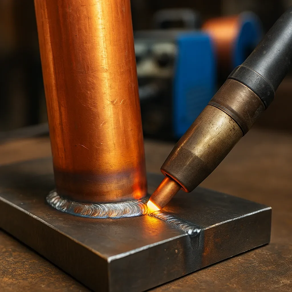
You can MIG weld copper, but it requires excellent heat control, high electrical capacity, suitable filler wire, and thorough surface cleaning.
At first glance copper seems like an easy metal to join because it is soft ductile and melts at a lower temperature than steel The counterintuitive problem is.
There is no single setting that works for every copper job Thickness alloy joint design machine output wire diameter shielding gas and whether the part is a bus. This guide examines “how to mig weld copper” and explains the details that matter in practice.
You will also see how to recognize common failures protect yourself from electrical and fume hazards and test a joint before trusting it The goal is not merely.
- ✓Copper’s high thermal conductivity makes heat control more important than simply increasing voltage.
- ✓Clean metal, correct polarity, a suitable filler, and adequate shielding are essential for stable transfer.
- ✓Preheating can help thick copper, but it must be controlled to avoid distortion, oxidation, and damage nearby.
- ✓Silicon-bronze MIG brazing is often easier for thin copper or dissimilar-metal joints than melting the copper base.
- ✓A weld should be inspected and, where safety or pressure matters, tested before it is put into service.
Why MIG welding copper is difficult
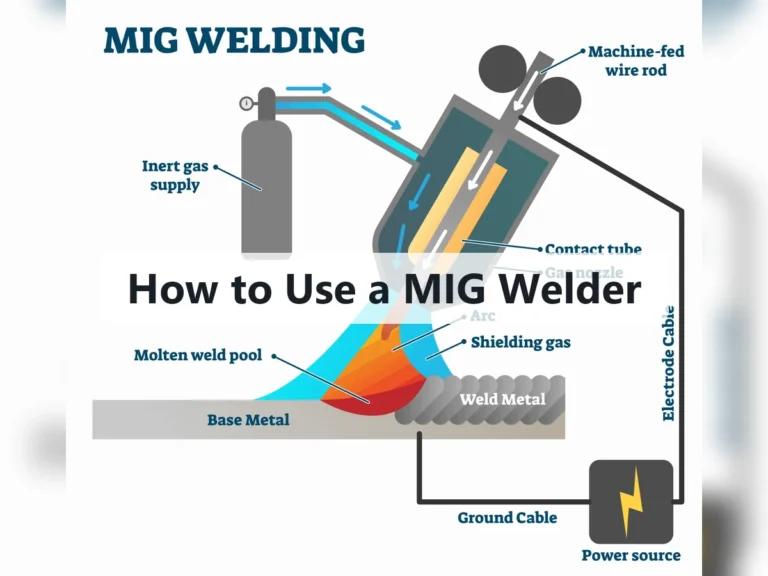
MIG welding technically called gas metal arc welding GMAW uses a continuously fed wire electrode and an arc to melt the filler and some of the base metal.
Copper also reflects radiant heat and can develop surface oxides or contamination that interfere with wetting If the work clamp is poor the electrical path becomes unstable while.

- Heat moves fast: A large copper part acts like a heat sink, pulling energy away from the arc and delaying fusion.
- Surface condition matters: Oil, oxide, paint, solder, and fingerprints can cause porosity or incomplete bonding.
- Appearance can mislead: A smooth bead may sit on top of the copper without adequate penetration.
- Alloy changes the job: Brass, bronze, oxygen-free copper, and copper alloys do not behave identically.
Know whether the part is actually copper
Before selecting a process, identify the base material as accurately as possible. Pure copper is highly conductive and often demands substantial heat. Copper alloys may contain zinc, tin, silicon, nickel, chromium, or other elements that change melting behavior, strength, fumes, and weldability.
Do not weld over copper-plated steel without removing the coating at the joint and confirming the underlying metal Likewise copper tubing may have oil flux residue lacquer or.
Decide whether fusion welding is necessary
Some applications need the base copper to melt and fuse with the filler. Others only need a strong, conductive or mechanically secure connection. For the second group, MIG brazing with silicon-bronze wire may reduce distortion and base-metal melting, particularly on thin sheet or copper-to-steel joints.
Brazing is not automatically suitable for every electrical pressure structural or high-temperature application The joint must be designed for the filler s strength conductivity service temperature and corrosion.
How to MIG weld copper: equipment and material choices
Successful work starts before the torch reaches the joint A machine that performs well on mild steel may not have enough output duty cycle inductance control or wire-feeding.
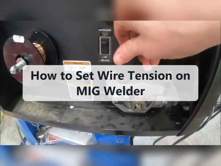
A spool gun or push-pull gun is often helpful because soft copper and aluminum-type wires can bird-nest in a long standard liner. Keep the gun cable as straight as practical, use the correct liner and contact tip, and avoid excessive drive-roll pressure. The wire should feed consistently without flattening or shaving.
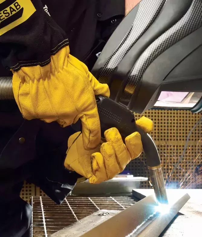
- Machine capacity: Confirm the output, duty cycle, polarity options, and wire diameter range for the planned thickness.
- Feeding path: Use a suitable liner, drive rolls, contact tip, and short, smooth gun path for soft wire.
- Filler selection: Match the wire to the copper alloy, joint purpose, and required strength or conductivity.
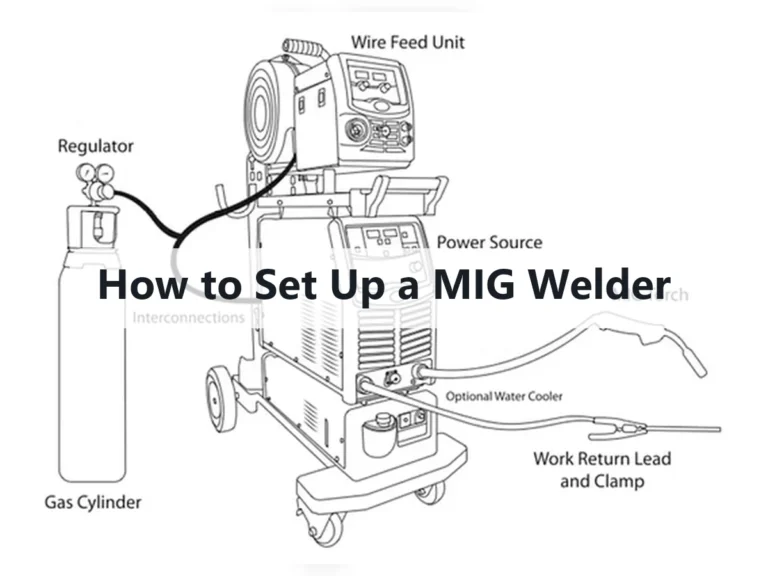
- Gas delivery: Check regulator, hose, flow, leaks, and protection from drafts before striking an arc.
Choose a filler wire
The filler should be selected by application rather than color Copper wire can provide a copper-rich weld but it may be difficult to feed and may demand substantial.
Bronze and copper-alloy wires vary in silicon, tin, manganese, aluminum, or other content. Those differences affect fluidity, color, strength, conductivity, corrosion resistance, and compatibility with the base metal. For a critical joint, follow the filler manufacturer’s compatibility guidance and the requirements of the equipment or industry involved.
| Job condition | Common direction | Main caution |
|---|---|---|
| Pure copper to copper | Copper-compatible filler and a high-heat-capacity setup | Cold fusion is common if the workpiece acts as a heat sink |
| Thin copper sheet | Short-circuit control or silicon-bronze brazing where appropriate | Burn-through and warping can occur quickly |
| Copper to steel | Silicon-bronze MIG brazing is often considered | Joint design and service requirements determine suitability |
| High-conductivity electrical joint | Use a filler and procedure approved for the electrical purpose | Mechanical appearance does not prove low resistance |
Select shielding gas and polarity
Gas selection depends on the wire and transfer mode. Argon is common for many nonferrous applications, while helium or argon-helium blends can provide a hotter arc and may help on thick, highly conductive copper. A gas that works for silicon bronze may not be the best choice for pure copper wire.
Most solid-wire MIG welding uses direct current electrode positive (DCEP), but the correct polarity belongs to the wire and process data. Verify it rather than assuming every copper operation uses the same connection. Incorrect polarity can produce unstable transfer, excess spatter, poor wetting, and an erratic arc.
Shielding flow must protect the puddle without creating turbulence. Excessive flow can draw air into the shield, while too little flow leaves the weld vulnerable to porosity. Protect the work from fans and open doors, and remember that gas flow is not a substitute for cleaning.
Preparing copper for a MIG weld
Preparation often determines the result more than a small voltage adjustment. Remove paint, plating, oxide, oil, adhesive, marker, and solder from both sides of the joint. Use a dedicated stainless-steel brush, abrasive pad, or suitable mechanical method reserved for copper so you do not embed iron particles in the surface.
After mechanical cleaning, wipe the joint with an appropriate solvent and allow it to evaporate fully. Keep the cleaned area protected from handling until welding. For tubing or hollow components, consider whether internal contamination, trapped solvent, or pressure could create a hazard when heated.
- Fit-up: Close excessive gaps, align the parts, and use a joint design that gives the arc access to the root.
- Contact surfaces: Clean the joint and the work-clamp location down to bright, sound metal.
- Heat sinks: Identify connected copper masses, fixtures, and bars that may pull heat away.
- Protection: Remove or shield insulation, seals, coatings, and electronics that could be damaged by preheat or spatter.
Joint design and fit-up
A butt joint in thin sheet behaves differently from a fillet on thick plate On heavy copper a bevel or a prepared groove may be needed to reach.
Use copper-compatible backing or a heat-resistant fixture when it improves support and controls the puddle A backing bar can also draw away heat so it may help thin.
Preheating without losing control
Preheating a thick copper assembly can reduce the temperature difference between the arc zone and the surrounding material That lets more of the arc s energy support fusion.
Use a temperature-indicating crayon, contact thermometer, or approved infrared method as appropriate, remembering that shiny copper can give unreliable infrared readings. Heat broadly and evenly rather than creating a small, excessively hot spot. Never use an uncontrolled torch flame near combustible insulation, sealed cavities, or components that cannot tolerate heat.
When the part is already warm from service, isolate power sources and confirm it is safe to handle. Copper can remain dangerously hot while looking unchanged, so plan where the work will cool and how it will be moved.
How to set up and weld the joint
Once the joint is clean and supported install the correct wire polarity liner contact tip and shielding gas Set the machine according to the wire manufacturer s data.
Use the shortest practical stickout and keep the gun angle consistent The exact contact-tip-to-work distance depends on the wire and process so use the applicable welding data rather. This distinction matters when answering “how to mig weld copper”.
- Secure the work: Clamp the pieces firmly, establish a clean electrical return path, and confirm that the assembly cannot shift as it heats.
- Make a controlled test: Run a short bead or tack on comparable copper and inspect wetting, penetration, spatter, and wire feeding.
- Start with steady motion: Establish the arc on sound metal and move at a speed that keeps the puddle small but connected to both sides.
- Watch the edges: Pause only as needed to fuse the joint; excessive dwelling can melt through thin copper or overheat the surrounding area.
- Clean and inspect: Remove residue or spatter as appropriate, allow the weld to cool safely, and examine it before continuing.
- Favor consistency: A stable gun angle, stickout, and travel speed are more useful than constant dial changes.
- Use short beads: On thin or distortion-sensitive work, segmented welds can limit heat buildup.
- Adjust one variable: Change voltage, wire speed, travel speed, or preheat method one at a time so the effect is clear.
- Keep a record: Note material, wire, gas, polarity, settings, preheat, and joint behavior for repeat work.
What the puddle should tell you
A useful puddle should visibly wet the joint edges and advance in a controlled way If filler piles up ahead of the arc the travel may be too.
For a fillet, avoid placing all the heat on one leg. For a butt joint, keep the arc centered enough to fuse both edges while maintaining the root. Copper can remain shiny and fluid for longer than expected, so do not judge temperature by color alone.
When a pulsed process helps
A pulsed MIG program can help manage heat input and transfer on some machines, particularly where short-circuit transfer is unstable or spray transfer would put too much energy into thin material. Pulse settings are highly machine- and wire-specific; a generic pulse frequency or peak-current value is not a reliable recipe.
If your welder has no suitable program and the job requires precise control, TIG, brazing, or a qualified fabrication process may be more practical. The best method is the one that produces the required joint with controllable heat, not necessarily the one already loaded in the machine.
Common problems and troubleshooting
Many copper weld defects have more than one possible cause Correct diagnosis starts with the appearance of the bead the behavior of the arc the joint s thickness.
- Copying steel settings: Steel data may not provide enough heat or the right transfer behavior for copper.
- Skipping cleaning: Oxide, oil, and plating can create porosity and prevent wetting.
- Overfeeding soft wire: Excessive drive-roll pressure can deform wire and cause bird-nesting.
- Trusting a shiny bead: Surface smoothness cannot confirm root fusion or electrical performance.
| Observed problem | Likely contributors | Checks and corrections |
|---|---|---|
| Cold lap or bead sitting on top | Insufficient heat, fast travel, poor fit-up, large heat sink | Check output, joint access, preheat, travel, and comparable test material |
| Burn-through | Too much heat, excessive dwell, large root gap, thin edge | Reduce heat input, improve fit-up, shorten beads, or consider brazing |
| Porosity | Contamination, drafts, poor gas flow, damp or damaged hose | Reclean, check leaks and flow, shield the area, and inspect the regulator |
| Wire bird-nesting | Wrong liner, excessive drive pressure, blocked tip, feeding resistance | Use the correct components, reduce pressure, straighten the gun path |
| Excessive spatter | Wrong polarity, unstable settings, poor contact, unsuitable gas | Verify process data, polarity, tip condition, and gas selection |
| Cracking after cooling | Unsuitable filler, restraint, contamination, thermal stress | Review alloy and joint design; do not repair blindly over a crack |
Incomplete fusion and lack of penetration
Incomplete fusion is particularly dangerous because the bead may look continuous On a test coupon cut and etch a cross-section if you have the equipment and knowledge to.
To improve fusion verify the joint is not too cold the surfaces are bright and clean and the arc can reach the root More preheat may help a.
Porosity and discoloration
Porosity may appear as pinholes, surface craters, or internal voids. Look first for oil, moisture, oxide, trapped solvent, inadequate shielding, drafts, and leaks between the regulator and gun. A gas nozzle clogged with spatter can disturb flow even when the regulator shows the expected reading.
Color changes are not always a defect, but unusual dark deposits, roughness, or heavy oxidation can indicate poor shielding or overheating. Clean the surface and compare a new test bead under stable conditions before deciding whether the problem is the filler, gas, or base metal.
Electrical and dimensional checks
For conductive components, measure resistance or perform the required electrical test after the joint has cooled and been cleaned. A weld can be mechanically sound yet unsuitable as a low-resistance connection if the filler or contact geometry does not meet the application.
For tubing and pressure-containing parts use the applicable leak or pressure test and protect the assembly from unsafe stored energy For structural parts visual inspection alone may not satisfy the design or governing requirements When consequences of failure are serious have the procedure and inspection method established by a.
Safety, ventilation, and post-weld care
Arc welding copper involves intense ultraviolet radiation hot metal sparks compressed gas and electrical energy Copper and its alloys may also generate hazardous fumes especially when coatings plating.
Use local exhaust ventilation or an effective fume-control system that captures contaminants without disturbing shielding gas. Never weld on containers, lines, or components that may contain flammable material, refrigerant, fuel, solvent, or pressure. Disconnect batteries, capacitors, energized conductors, and sensitive electronics before attaching the work lead.
- Ventilation: Keep your breathing zone clear of fumes and identify coatings or alloy constituents before heating.
- Fire control: Remove combustibles, inspect the opposite side of the work, and keep suitable extinguishing equipment available.
- Electrical isolation: De-energize connected systems and place the return clamp where current will not pass through bearings or electronics.
- Heat awareness: Mark hot copper, let it cool in a controlled area, and do not handle it based only on appearance.
Protect nearby insulation and hardware
Copper is often part of an assembly containing rubber seals plastic insulation soldered connections circuit boards or plated fasteners Heat can travel well beyond the visible joint so.
After welding, inspect for arc strikes, spatter, sharp edges, distortion, and damaged coatings. Restore insulation, corrosion protection, and sealing only after the joint has passed the required checks.
Cleaning and maintenance
Allow the assembly to cool before aggressive cleaning or dimensional correction. Remove loose residue with a method compatible with the base and filler; avoid embedding abrasive particles or spreading contamination into a clean electrical contact.
Maintain the welder by checking the liner, drive rolls, contact tip, ground clamp, torch nozzle, gas hose, and connections. Soft wire can reveal a marginal feeding system quickly, so replace worn parts before the next job rather than compensating with excessive drive pressure.
When MIG is the wrong process
MIG is attractive for production speed and long repeatable welds but it is not always the most controllable method for copper TIG provides a more focused arc and.
Silicon-bronze MIG brazing can be useful when minimizing base-metal melting is more important than achieving a copper-fusion weld. Oxyfuel methods, resistance welding, soldering, or mechanical joining may also fit particular designs, but each has limits involving strength, conductivity, heat, joint clearance, and service temperature.
- Choose MIG: When access, production speed, machine capacity, and heat control support the joint requirements.
- Consider TIG: When precision, thin material, puddle control, or appearance matters more than deposition rate.
- Consider brazing: When joining dissimilar metals or limiting melting of a thin copper base is important.
- Stop and qualify: When the joint is structural, pressure-containing, safety-critical, or part of a high-current system.
Why one-size-fits-all advice fails
The phrase how to mig weld copper covers radically different jobs. A thin decorative sheet, a two-inch copper plate, a refrigerant tube, and an electrical bus bar cannot share one universal wire speed, gas flow, preheat, travel speed, or inspection method.
Even two parts of the same thickness may need different settings if one is clamped to a large copper fixture or connected to a heat sink. Treat published settings as a starting range, then qualify the actual combination of alloy, joint, machine, filler, and thermal mass.
FAQ: how to MIG weld copper
Can a standard MIG welder weld copper?
Sometimes, provided it has adequate output, suitable polarity and controls, compatible wire, reliable shielding gas, and a stable feeding system. A basic machine may struggle with thick copper or soft wire, especially through a long gun liner.
Test on copper with similar thickness and thermal mass. If the arc cannot remain stable or the joint repeatedly lacks fusion, a different machine or process is warranted.
What gas is best for MIG welding copper?
Argon is commonly used for many nonferrous wires, while helium or argon-helium blends may add heat for some thick-copper applications. The correct gas depends on the filler, transfer mode, alloy, and machine data.
Use the wire manufacturer’s gas recommendation whenever available. Avoid drafts and excessive flow, because disturbed shielding can cause porosity even when the selected gas is appropriate.
Should copper be preheated before MIG welding?
Thick copper often benefits from controlled preheating because it conducts arc heat away rapidly. Thin copper may not need preheat and can burn through if heated too aggressively.
Preheat broadly and monitor it with an appropriate temperature method. The allowable temperature depends on the alloy, joint, nearby materials, and service requirements, so do not treat a single temperature as universal.
Can I use regular steel MIG wire on copper?
No. Steel wire is not a suitable general-purpose filler for a copper weld. It can create an incompatible deposit, poor wetting, weak or brittle areas, and corrosion or electrical problems.
Select copper-compatible wire or an appropriate silicon-bronze filler for a brazing application. Confirm compatibility before welding copper alloys or dissimilar metals.