How to Flux Core MIG Weld: Clear Instructions and Common Mistakes
Set up the welder with the correct flux-core wire and polarity, then weld with a steady angle, travel speed, and stickout while controlling heat.
Flux-cored arc welding uses a continuously fed wire whose internal flux creates shielding as it burns. That makes the process practical for outdoor repairs, thicker steel, and situations where a separate shielding-gas cylinder would be inconvenient. It can also produce strong, useful welds with relatively simple equipment.
However learning how to flux core mig weld is not simply a matter of pulling the trigger and moving the gun along the joint A rushed setup can.
Many beginners assume flux-core welding is automatically more forgiving than solid-wire MIG welding It is often tolerant of wind and surface contamination but that does not mean it ignores incorrect settings or poor technique This guide.
- ✓Use the wire manufacturer’s polarity and parameter guidance; self-shielded flux-core wire commonly runs on DC electrode negative, but not every wire does.
- ✓Clean the joint, remove mill scale where practical, and maintain consistent stickout and travel speed.
- ✓Drag self-shielded flux-core wire rather than pushing it, and remove slag between passes.
- ✓Control heat by balancing voltage, wire-feed speed, travel speed, joint design, and the thickness of the base metal.
What You Need Before You Flux-Core Weld
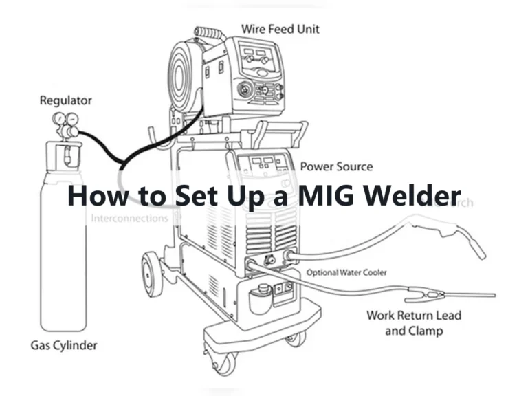
A flux-core setup starts with more than a welding machine. You need a compatible wire spool, a sound work lead, the correct contact tip, a suitable gun liner, and a clean, stable work surface. Inspect the machine’s duty cycle and output range before attempting a long weld or a joint near the upper limit of its capacity.
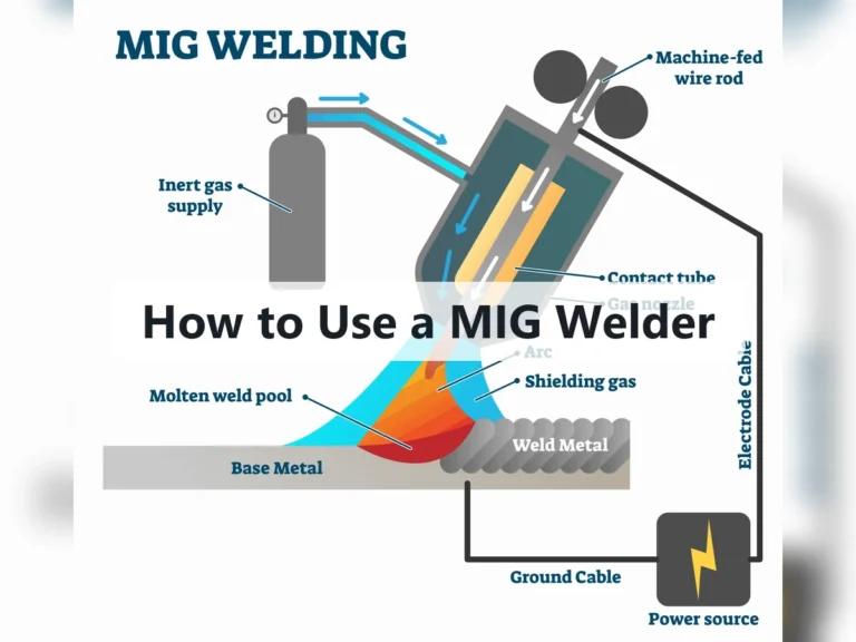
There are two broad wire categories. Self-shielded flux-cored wire produces its own shielding and is the type most people mean when discussing outdoor flux-core welding. Gas-shielded flux-cored wire uses a shielding-gas cylinder as well as flux, so it requires different connections, settings, and handling.
Never assume the same polarity or gas applies to both.
- Wire classification: Read the spool label and machine instructions for the wire’s intended steel type, polarity, and operating range.
- Wire diameter: Match the contact tip, drive-roll groove, liner, and machine settings to the spool.
- Machine capacity: Confirm that the welder can provide the required current without exceeding its duty cycle.
- Consumables: Replace a worn contact tip or damaged liner before diagnosing an arc problem.
Choose the Correct Flux-Core Wire
Wire selection depends on the base metal, thickness, welding position, and whether you need outdoor performance. A common self-shielded mild-steel wire may be appropriate for general fabrication, but specialty wires can differ in strength, penetration, position capability, and slag behavior.
Smaller wire is often easier to control on thin material, while larger wire can deposit metal faster and suit heavier work. The spool’s label is more reliable than a generic chart because manufacturers may specify different voltage, wire-feed speed, polarity, and stickout ranges for similar-looking products.
Polarity Matters
Flux-core wire is not automatically used on one polarity. Many self-shielded wires are designed for DC electrode negative, also called straight polarity, while many gas-shielded flux-core wires use DC electrode positive. Reversing the leads when the wire requires a different arrangement can create an unstable arc, excess spatter, poor penetration, or an unusable bead.
Check both the wire label and the welder’s polarity connections. If the machine has internal lead connections, follow its manual rather than relying on a color alone. Polarity is a setup decision, not a fine adjustment to make after the weld already looks wrong.
Safety Equipment and Work Area
Wear a properly rated welding helmet, flame-resistant clothing, leather gloves, sturdy boots, and hearing protection where appropriate. Flux-core welding creates intense ultraviolet light, hot slag, fumes, and sparks that can travel farther than expected. Keep exposed skin covered and protect nearby people with welding screens.
Remove flammable materials from the work area provide appropriate ventilation and never weld on containers or metal that may have held fuel solvents or other hazardous substances unless.
How to Flux Core MIG Weld: Setup and Technique
The most reliable method is to establish the machine and joint before starting the arc. Secure the work, position the gun so you can see the leading edge of the puddle, and make a short practice weld on similar scrap. That test reveals whether the arc is stable and whether the chosen settings are close enough to refine.
Self-shielded flux-core welding usually requires a drag technique. The gun points slightly back toward the completed weld, and you move it in the direction that leaves the puddle behind the wire. Pushing the gun can place the shielding and slag in the wrong relationship to the molten metal, increasing the chance of porosity or an irregular bead.
- Install the spool: Feed the wire through the correct drive-roll groove and liner without kinks or sharp bends.
- Confirm polarity: Connect the work lead and gun according to the wire manufacturer’s instructions.
- Prepare the joint: Remove oil, loose rust, paint, moisture, and excessive scale from the weld area.
- Test on scrap: Adjust within the recommended range before welding the actual part.
Loading the Wire
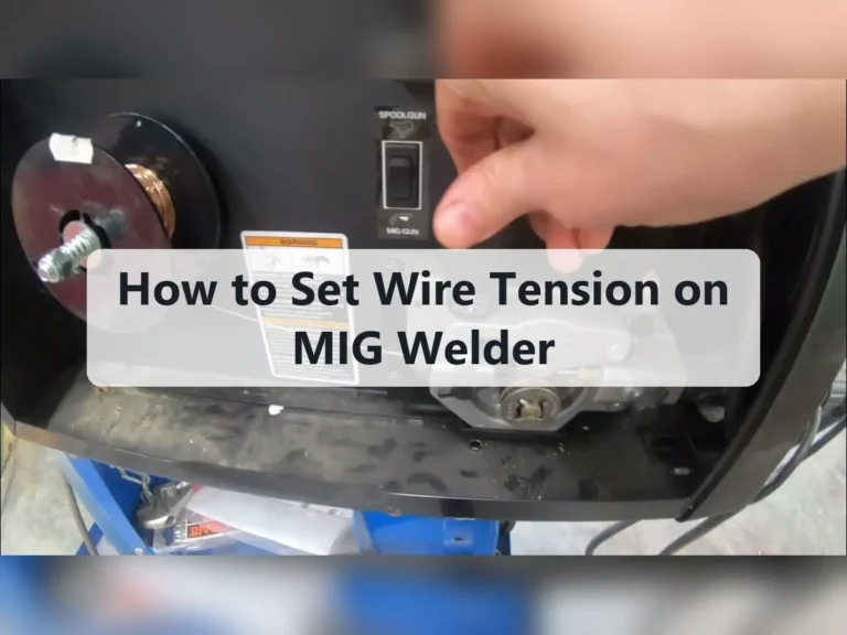
Install the spool so the wire unwinds in the direction shown by the machine. Set the drive-roll tension only high enough to feed the wire consistently. Too much tension can flatten the wire or strain the motor; too little allows the roll to slip when the wire meets resistance.
Use the correct knurled drive roll for many self-shielded flux-core wires. A smooth roll intended for solid MIG wire may slip, while excessive pressure from the wrong roll can damage the wire. Snip the wire end cleanly, guide it into the liner, and hold the gun cable as straight as practical while feeding.
Set Stickout, Angle, and Travel
Stickout is the exposed wire length between the contact tip and the workpiece. Flux-core wire often uses a longer stickout than solid MIG wire, but the correct value depends on the specific wire. Use the spool instructions as your starting point and keep the distance consistent rather than allowing the gun to drift toward and away from the joint.
Hold the gun at roughly a 10- to 15-degree drag angle for many self-shielded applications. The exact angle may vary with position and joint geometry, but an extreme angle can trap slag, reduce visibility, or disturb the shielding. Keep the arc aimed at the leading edge of the puddle instead of the cold area ahead of it.
Travel speed should be fast enough to prevent an overly wide overheated puddle but slow enough to fuse both sides of the joint Listen for a consistent arc.
Run the First Bead
- Clamp the parts securely and connect the work clamp to clean metal close enough to provide a dependable circuit.
- Set the wire-feed speed and voltage or inductance near the middle of the manufacturer’s suggested range for the material thickness.
- Position the gun so the contact tip has the specified stickout and you can see the joint.
- Lower the helmet, start the arc at the intended weld location, and establish a small, controlled puddle.
- Drag the gun steadily along the joint, maintaining the angle, stickout, and travel speed.
- Release the trigger at the end, allow the weld to cool enough to handle, and chip or brush away slag.
For a simple fillet weld, aim the arc into the corner while distributing heat between both pieces. A slight pause at each side can improve sidewall fusion, but a large weaving motion often adds heat without improving the joint. On a narrow joint, a straight bead is usually easier to control.
Layering and Multi-Pass Work
Thicker joints may require multiple passes rather than one oversized bead. A root pass establishes fusion, and later passes fill the joint. Clean all visible slag between passes; trapped slag can become an inclusion that weakens the weld and may not be obvious from the surface.
Use a bead sequence that limits distortion, such as alternating sides or short sections when appropriate. Avoid placing a large amount of heat into one area continuously. If the joint requires a specific strength, penetration, or inspection standard, follow the applicable welding procedure rather than relying on appearance alone.
This distinction matters when answering “how to flux core mig weld”.
Settings, Joint Preparation, and Heat Control
Voltage and wire-feed speed work together, but they do not have identical functions. Wire-feed speed primarily influences amperage and deposition rate, while voltage influences arc length and bead profile. On many machines, changing one affects the way the other behaves, so make small adjustments and test each change.
Start with the wire manufacturer’s chart, then use the sound and shape of the arc to refine the setting. A harsh, erratic arc may indicate incorrect voltage, poor grounding, an unsuitable stickout, or a feed problem. A smooth sound alone does not prove adequate penetration, so inspect the bead and practice on material with the same thickness and joint design.
- Too much heat: Watch for burn-through, excessive bead width, undercut, distortion, or a puddle that is difficult to control.
- Too little heat: Look for a tall bead, poor wetting, cold lap, and inadequate fusion at the joint edges.
- Too much wire: A stubbing or pushing arc can result when wire-feed speed is high for the selected voltage.
- Too little wire: An overly long, unstable arc may occur when voltage is high relative to wire-feed speed.
Joint Fit-Up and Material Thickness
Good fit-up reduces the amount of filler metal and heat needed. Large gaps may require slower travel or multiple passes, but they also increase burn-through risk on thin stock. Tight, consistent joints make it easier to maintain a stable puddle and produce repeatable results.
For thicker material, beveling may be necessary to create access and achieve fusion through the joint. Remove sharp edges, scale, paint, and contaminants from the bevel and surrounding area. A strong-looking cap over an unfused root is not a sound weld.
Work Angles by Joint Type
| Joint | Useful starting position | What to watch |
|---|---|---|
| Fillet joint | Aim near the corner and divide heat between both plates | Unequal legs, undercut, or slag trapped at the toe |
| Butt joint | Center the arc over the seam or root opening | Burn-through, lack of root fusion, and excessive reinforcement |
| Lap joint | Favor the upper edge slightly while melting into both pieces | Cold lap along the lower plate or excessive overlap |
| Outside corner | Use a controlled puddle with limited weaving | Burn-through at the sharp edge and insufficient side fusion |
Position Changes
Flat-position welding is the easiest place to establish technique because gravity helps hold the puddle. In horizontal, vertical, or overhead positions, reduce the puddle size and adjust settings within the wire’s approved range. A shorter arc and controlled travel are generally more manageable than a wide, fluid puddle.
For vertical-up work, use a small weave or brief pauses at the sides if the wire and procedure allow it. Move fast enough across the center to keep the puddle from sagging. Overhead welding demands especially careful preparation, protective clothing, and control because hot slag can fall toward the operator.
Common Flux-Core Welding Mistakes and Their Causes
Most visible defects have several possible causes. Change one variable at a time whenever possible so you can identify the real problem. Before adjusting voltage, check the simpler issues: polarity, grounding, wire condition, liner restriction, stickout, and surface contamination.
The phrase how to flux core mig weld describes a process that looks similar to MIG welding, but the flux changes the way you manage the arc and finished bead. Slag must be removed, wind can still disturb shielding, and the wire’s recommended polarity may differ from solid-wire practice.
- Pushing self-shielded wire: This can place the gun ahead of the protective flux action and encourage porosity or slag entrapment.
- Skipping cleaning: Oil, moisture, paint, and heavy scale can create gas pockets and prevent fusion.
- Changing several settings: Multiple adjustments hide the cause of a defect and make repeatable tuning difficult.
- Welding over slag: The next pass may trap nonmetallic material instead of bonding to clean steel.
Porosity and Worm Tracks
Porosity appears as holes or pinholes caused by gas becoming trapped in the solidifying weld. Wind, damp or contaminated material, excessive stickout, wrong polarity, and poor slag coverage can all contribute. Move to a sheltered area, dry the material appropriately, clean the joint, and verify the wire’s setup.
Worm tracks are elongated marks associated with gas escaping through the solidifying slag. They can result from excessive voltage, a long stickout, contamination, or travel and parameter combinations that allow gas to remain trapped. Compare your settings with the spool guidance and make a small controlled change.
Undercut, Cold Lap, and Lack of Fusion
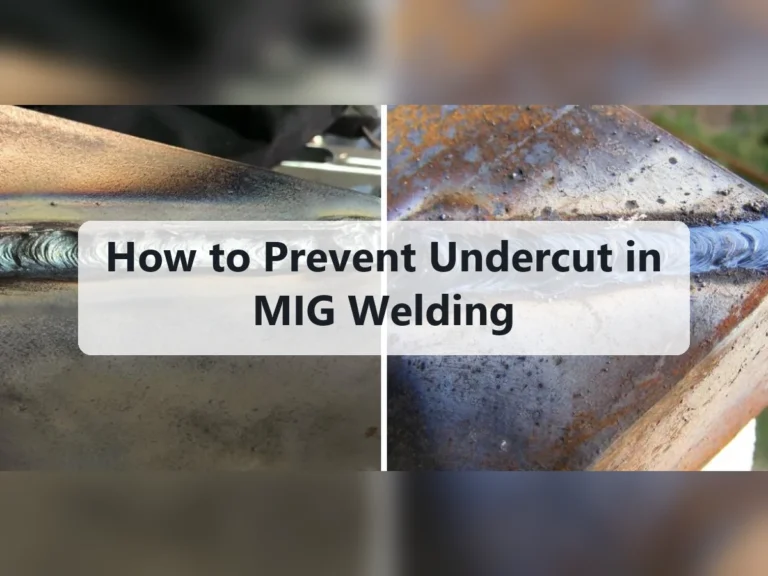
Undercut is a groove melted into the base metal beside the bead and left unfilled. Excessive travel speed, too much voltage, a long arc, or poor sidewall control may cause it. Slow slightly, reduce heat if appropriate, and pause just enough at the toes to fill the edges.
Cold lap occurs when filler metal overlaps the base metal without properly fusing to it. It often comes from a cold setting, an incorrect angle, or moving too quickly. Aim the arc at the joint, not merely at the surface of the previously deposited metal.
Excessive Spatter or Irregular Feeding
Some spatter is normal with flux-core welding, but a violent, inconsistent arc suggests a problem. Check whether the wire is feeding smoothly, the contact tip is the correct size, the drive rolls are gripping correctly, and the ground connection is clean and tight.
A spool that has absorbed moisture or developed surface corrosion may feed poorly and produce unstable welds. Store wire in a dry, protected location and replace questionable consumable wire rather than trying to compensate with extreme machine settings.
Inspection, Cleanup, and Troubleshooting
Let the weld cool enough to handle before chipping slag. Use a chipping hammer and wire brush appropriate to the work, and wear eye protection because slag fragments can fly. Do not judge the weld until the slag and spatter that hide its edges have been removed.
Inspect the bead for consistent width, smooth transitions, adequate fusion at both toes, cracks, craters, excessive reinforcement, and visible pinholes. Visual inspection cannot reveal every internal defect, but it can identify many technique and setup problems before the part is used.
- Arc will not start: Check power, trigger operation, ground connection, wire contact, and polarity.
- Wire burns back: Look for excessive stickout, a restricted tip, low wire-feed speed, or a feed interruption.
- Wire bird-nests: Reduce drive-roll tension, inspect the liner, and check for a blocked contact tip.
- Bead is too tall: Increase travel speed slightly or adjust voltage and wire-feed speed within the approved range.
Crater Control
Stopping abruptly can leave a crater, a concave depression that may crack as the weld cools. At the end of a bead, briefly back up or pause according to the machine and wire procedure so the crater is filled. Avoid leaving an unprotected molten spot after releasing the trigger.
When a Weld Should Be Removed
Remove and reweld a bead that has visible cracks, major porosity, lack of fusion, severe undercut, or slag trapped between passes. Grinding away only the surface may leave the defect below it. For a load-bearing, safety-critical, pressure-containing, or regulated component, obtain qualified guidance and use the required procedure and inspection method.
FAQ: How to Flux Core MIG Weld
Do you push or pull when flux-core welding?
For many self-shielded flux-core wires, pull or drag the gun so the arc leads into the joint and the slag follows behind. Always check the wire instructions because gas-shielded flux-core applications and specific procedures can differ.
Does flux-core welding require gas?
Self-shielded flux-core wire does not require an external shielding-gas cylinder. Gas-shielded flux-core wire does, so identify the wire type before connecting equipment or selecting polarity.
What polarity is used for self-shielded flux-core wire?
Many common self-shielded wires use DC electrode negative, but this is not universal. Read the spool label or manufacturer’s instructions and connect the gun and work leads accordingly.
Can flux-core welding be used outdoors?
Yes, self-shielded flux-core welding is often selected for outdoor work because it does not depend on a separate gas shield that wind can disperse. Wind can still affect the arc and carry fumes, so use a windbreak and confirm that the work area remains properly ventilated.
Why does my flux-core weld have so much spatter?
Possible causes include incorrect polarity, poor grounding, unsuitable voltage and wire-feed balance, excessive stickout, dirty material, or irregular wire feeding. Check the basic setup first, then adjust one parameter at a time using the wire manufacturer’s range.
How do you prevent slag inclusions?
Remove all slag between passes, maintain a controlled puddle, and avoid burying slag at the sides of a wide weave. Correct travel angle and speed also matter; the arc should fuse the joint rather than simply laying metal over an uncleared surface.
Can flux-core wire weld thin sheet metal?
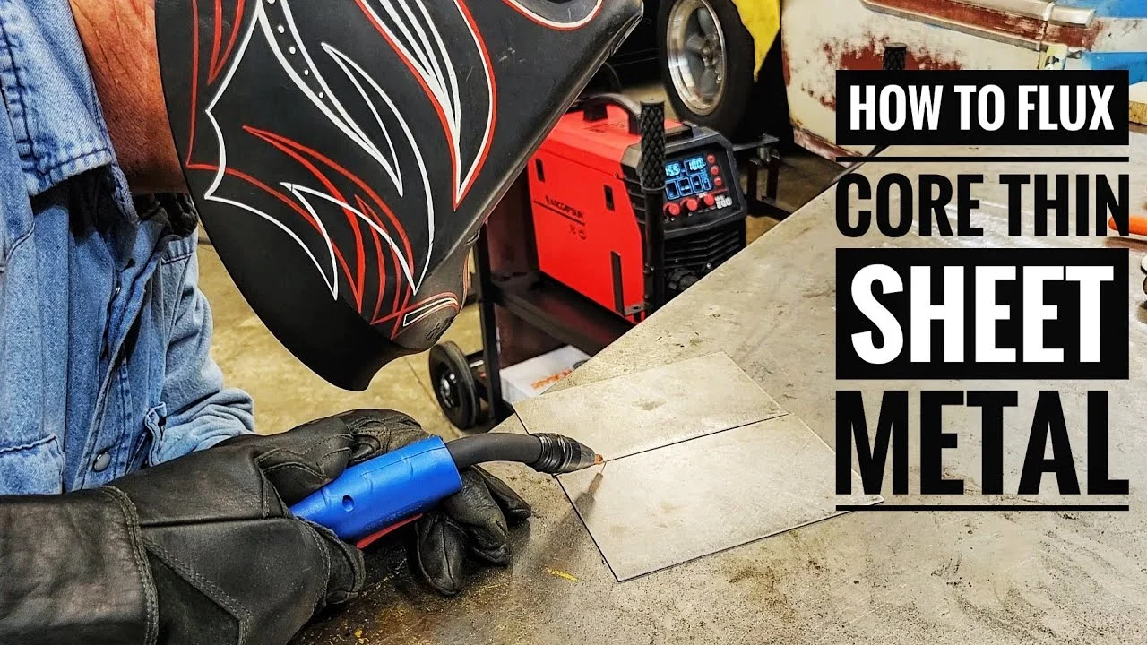
It can, but burn-through is a significant risk. Use the smallest suitable wire, short welds or stitch techniques where appropriate, tight fit-up, and settings intended for the material thickness. Practice on scrap before committing to the workpiece.
Conclusion
Successful flux-core welding comes from matching the wire to the machine, confirming polarity, preparing clean metal, and controlling the puddle with a consistent drag motion. The best answer to how to flux core mig weld is therefore a complete process rather than one machine setting: inspect the wire, test on similar scrap, weld in manageable passes, and clean and inspect every bead.
Flux-core welding can be productive and durable, but it is not risk-free or automatically suitable for every joint. Use ventilation and protective equipment, avoid questionable materials and unsafe containers, and seek qualified welding guidance when a failure could injure someone or damage critical equipment.
Install the correct wire, verify its polarity, and make a short test bead on clean scrap before welding the actual joint.