How Not to Weld Most Common MIG Welding Mistakes: Essential Guide
Avoid the most common MIG welding mistakes by controlling setup, gas flow, wire speed, travel technique, cleanliness, and safety before striking an arc.
MIG welding often looks easier than it is because the machine feeds wire automatically Counterintuitively that convenience can hide errors a weld may appear smooth while having poor.
Learning how not to weld most common mig welding mistakes starts before the gun reaches the workpiece Correct polarity suitable shielding gas clean base metal a stable ground.
This guide explains the failures that cause weak or unattractive MIG welds how to recognize them and which correction to make first You will learn how settings fit-up.
- ✓Clean metal, correct polarity, solid grounding, and adequate shielding gas solve many apparent technique problems.
- ✓Wire speed and voltage must work together; changing only one can create an unstable arc.
- ✓Excessive travel speed, long stickout, and poor gun angles commonly produce shallow fusion or porosity.
- ✓Visible appearance is not proof of strength, so questionable welds should be inspected and repaired rather than covered.
How Not to Weld Most Common MIG Welding Mistakes?
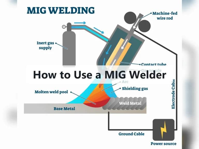
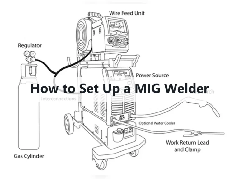
The most efficient troubleshooting begins with the equipment, not the weld bead. A machine that is incorrectly configured can produce the same symptoms as poor technique, including excessive spatter, an erratic arc, burnback, and lack of penetration.
Before welding identify the base-metal type and thickness the wire diameter the shielding gas and the joint design Then confirm that the machine settings are intended for that.
- Polarity: Verify the lead arrangement required by the wire; solid MIG wire commonly uses electrode positive, while some self-shielded flux-cored wires use a different arrangement.
- Ground path: Clamp directly to clean metal or a sound welding table, not to painted, rusty, or loosely connected surfaces.
- Consumables: Match wire diameter, liner, contact tip, drive rolls, and shielding gas to the process.
- Machine condition: Inspect the gun cable, connections, drive system, gas hose, and regulator before assuming the operator is at fault.
Wrong polarity or incompatible wire
Polarity determines how current flows through the welding circuit and strongly affects arc behavior penetration and spatter Using the wrong polarity for the selected wire can create an.
Do not rely on memory if the wire type has changed Read the spool label and machine instructions then check the positive and negative connections inside the welder.
Incorrect wire-feed components
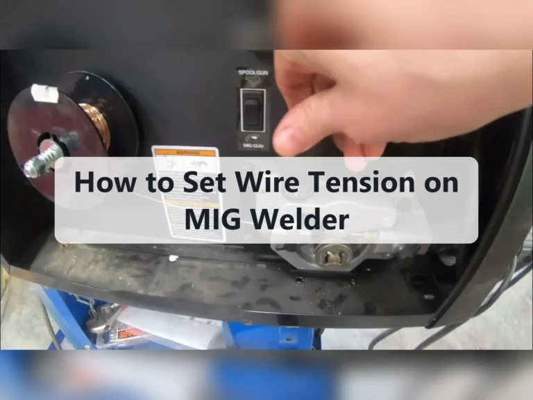
The drive rolls must suit the wire. A smooth roll is generally used for solid wire, while knurled rolls are commonly used for flux-cored wire. The wrong roll can slip, deform the wire, or create inconsistent feeding.
The contact tip should fit the wire diameter A tip that is worn partially blocked or too loose.
Poor grounding and dirty contact points
A weak ground connection can imitate a bad setting. Current may fluctuate, the arc may cut out, and spatter may increase. Paint, mill scale, rust, and oil between the clamp and workpiece restrict the return path.
Clean a small contact area and place the clamp as close to the weld as practical If the.
Shielding Gas and Cleanliness Errors That Cause Porosity
Porosity is the presence of gas pockets in the weld metal It may appear as pinholes on the surface but some porosity can remain hidden Shielding gas protects.
The common mistake is to treat gas flow as an isolated number Adequate coverage depends on the gas type nozzle condition wind torch distance leaks joint geometry and.
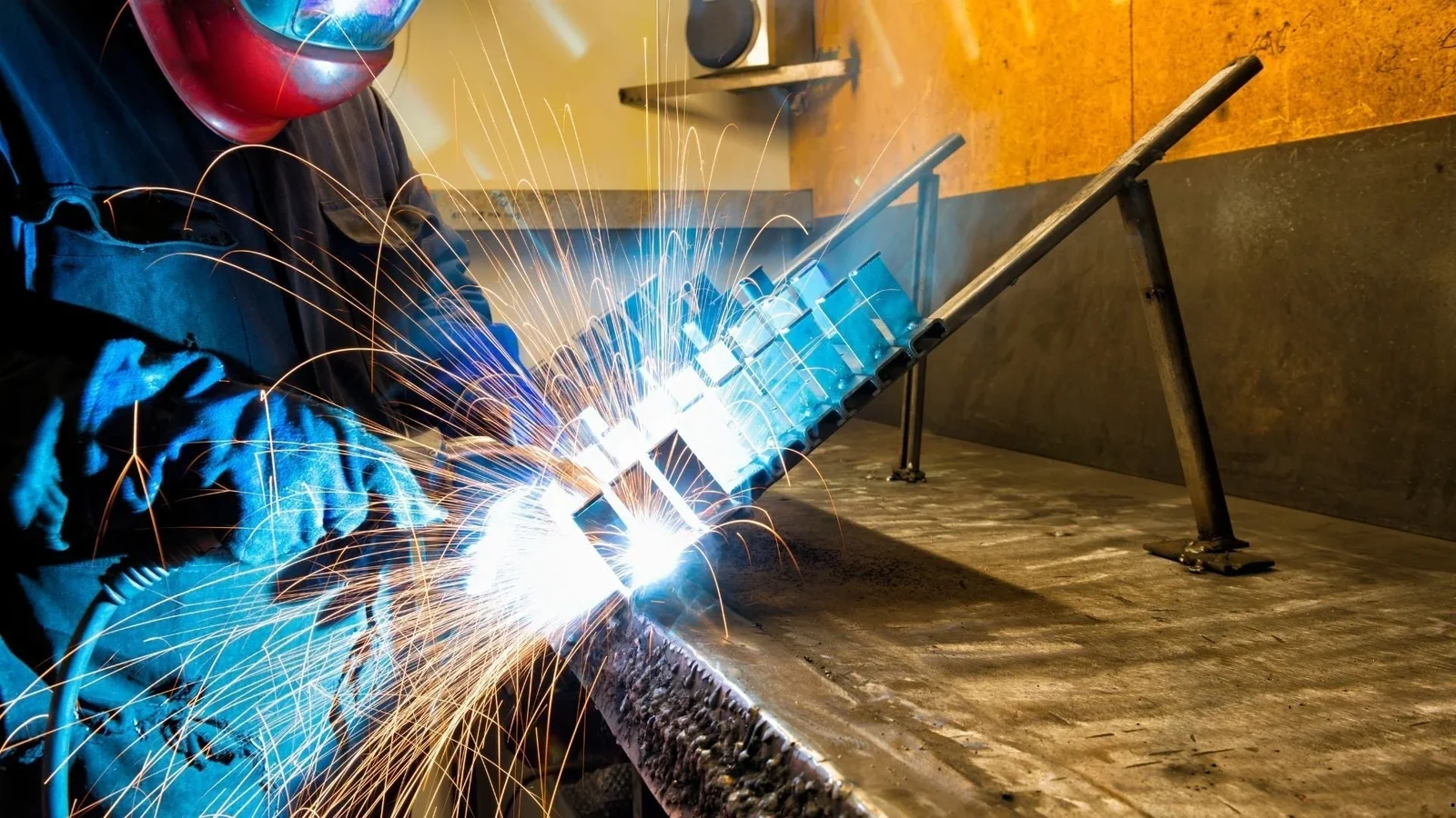
- Look for leaks: Inspect the cylinder connection, regulator, hose, fittings, solenoid, and gun neck with the system pressurized.
- Protect the arc: Shield the work from fans, open doors, and outdoor breezes that can disperse gas coverage.
- Clean thoroughly: Remove oil, paint, rust, moisture, and heavy mill scale from both sides of the joint.
- Inspect the nozzle: Clear spatter buildup and confirm that the diffuser and contact tip are properly installed.
Dirty base metal and contaminated wire
MIG wire does not eliminate the need for preparation Oil and coatings can release gases as they heat while rust and scale can prevent the molten filler from.
Grind or wire-brush the weld area to sound metal when appropriate, then remove abrasive dust and degreasing residue. Do not assume that a bright-looking surface is chemically clean; fingerprints, cutting fluid, and condensation can still cause defects.
Gas problems that are easy to miss
An empty cylinder closed valve damaged hose or faulty regulator can leave the operator with little or no shielding The flowmeter may show a reading while the gun.
Listen for leaks and confirm gas flow at the gun Keep the nozzle at a practical distance from the joint usually close enough for coverage without dragging it.
Wind and excessive gas flow
Outdoor MIG welding is especially vulnerable to wind Even a modest breeze can move shielding gas away from the arc causing pinholes and a gray irregular bead A.
If porosity appears after increasing gas flow, reduce the flow to the recommended range and look for turbulence. A large gas plume can pull air into the coverage area instead of improving it.
Wire Speed, Voltage, and Stickout: Finding a Stable Arc
Wire speed controls how much electrode enters the arc and is closely related to amperage Voltage influences arc length and bead shape These controls are linked so a change to one can require a corresponding. This distinction matters when answering “how not to weld most common mig welding mistakes”.
The most common mistake is to turn knobs randomly until the sound changes Instead begin with the chart settings for the material and wire weld a short test.
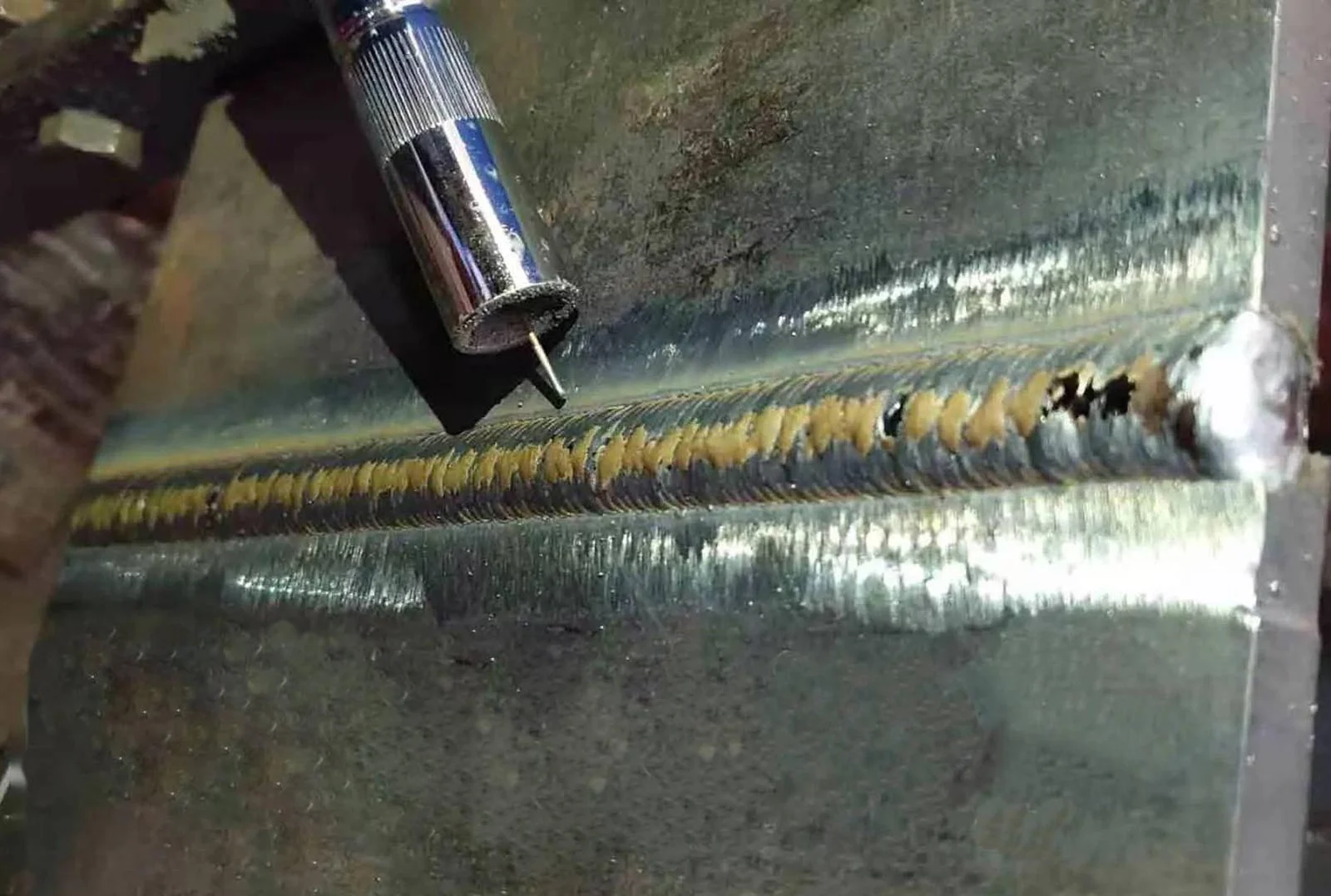
- Wire stubbing: Wire speed may be too high for the selected voltage, or the contact tip may be too close to the work.
- Long, wandering arc: Voltage may be too high, stickout may be excessive, or the gun may be held too far away.
- Burnback: Wire speed may be too low, stickout too short, or the tip worn or incorrectly sized.
- Heavy spatter: Check settings first, then inspect polarity, cleanliness, gas coverage, and the condition of the tip.
Too much wire speed
When wire speed is too high for the voltage the wire can repeatedly push into the puddle instead.
Reduce wire speed slightly or increase voltage within the appropriate range. Make small changes, because a large adjustment can create a long arc, excessive spatter, or an overheated joint.
Too little wire speed
Low wire speed can produce a long arc irregular deposition and insufficient filler metal The wire may melt before it reaches the puddle creating an unstable transfer pattern.
Increase wire speed gradually while maintaining the recommended voltage range. If the problem persists, inspect the liner and drive rolls for feeding resistance rather than continuing to increase the setting.
Excessive stickout
Stickout is the length of wire extending from the contact tip to the workpiece. Too much stickout increases electrical resistance before the wire reaches the arc, preheating the wire and reducing effective arc energy at the joint.
The result can be a cold narrow bead with poor fusion It also makes the gun harder to control and increases the chance that the shielding nozzle is.
Travel Speed, Gun Angle, and Bead Placement
Even correct machine settings cannot compensate for inconsistent hand movement Travel speed determines how much heat and filler.
Watch the leading edge of the puddle rather than only the finished bead The arc should remain directed into the joint and the pool should wet both sides.
- Keep movement consistent: Avoid sudden stops, acceleration, or wide loops that create uneven heat.
- Maintain the joint: Aim the arc where the pieces meet instead of merely placing wire on the easiest-to-see edge.
- Use a controlled angle: Keep the gun angle consistent and avoid extreme tilting that disrupts gas coverage.
- Pause deliberately: If a joint requires a weave, pause only enough at each side to fuse the toes without overheating them.
Moving too fast
High travel speed leaves too little heat and filler metal in each section of the joint Typical results include a narrow bead undercut along the toes poor sidewall.
Slow down enough for the puddle to wet both sides. If slowing creates excessive buildup or burn-through, the joint may need a different setting, fit-up, or technique rather than simply more travel control.
Moving too slowly
Low travel speed deposits too much metal and heat in one area. This can cause a tall convex bead, excessive penetration, burn-through on thin material, distortion, and undercut at the edges if the puddle becomes difficult to control.
Use shorter weld segments or a faster, more consistent travel rate when heat input is too high. On thin sheet, joint fit-up and intermittent welding may matter as much as the machine setting.
Push versus pull technique
With solid-wire MIG and shielding gas a slight push angle is commonly used because it provides a clear view of the joint and can produce a flatter bead.
Neither angle repairs poor preparation or incorrect settings. Choose a comfortable, consistent angle appropriate to the joint, and avoid extreme angles that move the nozzle away from the area being protected.
Joint Fit-Up, Tack Welding, and Heat Control
MIG welding mistakes are often blamed on the operator when the real problem is joint design A gap.
Fit the parts before welding and confirm that the joint can be reached with the gun at a workable angle Thin sheet may require tight control of gaps. Keep these limitations in mind when considering “how not to weld most common mig welding mistakes”.
- Control the gap: Keep the opening consistent and appropriate for the material thickness and joint type.
- Use adequate tacks: Place tacks where they resist movement without blocking the intended weld path.
- Plan the sequence: Alternate locations or directions when practical to reduce distortion.
- Check access: Ensure the gun, nozzle, and helmet view can reach the joint without forcing an unstable posture.
Bridging a gap with excess wire
Trying to fill a large or inconsistent gap with a high wire speed often creates a cold bridge rather than sound fusion The wire may span the opening.
Correct the fit-up when possible. If the design requires gap filling, use a suitable procedure with controlled heat, tacks, and passes rather than attempting to solve every problem with a single oversized bead.
Overheating thin material
Thin sheet can burn through when the arc remains in one place too long. Excessive heat also causes warping, which enlarges the gap and makes later welding more difficult.
Use short stitch welds skip around the panel allow cooling between sections and keep the puddle small Do.
Recognizing Weak or Defective MIG Welds
A smooth bead is only one observation A structurally sound weld requires adequate fusion suitable penetration acceptable profile and freedom from defects relevant to the application If the.
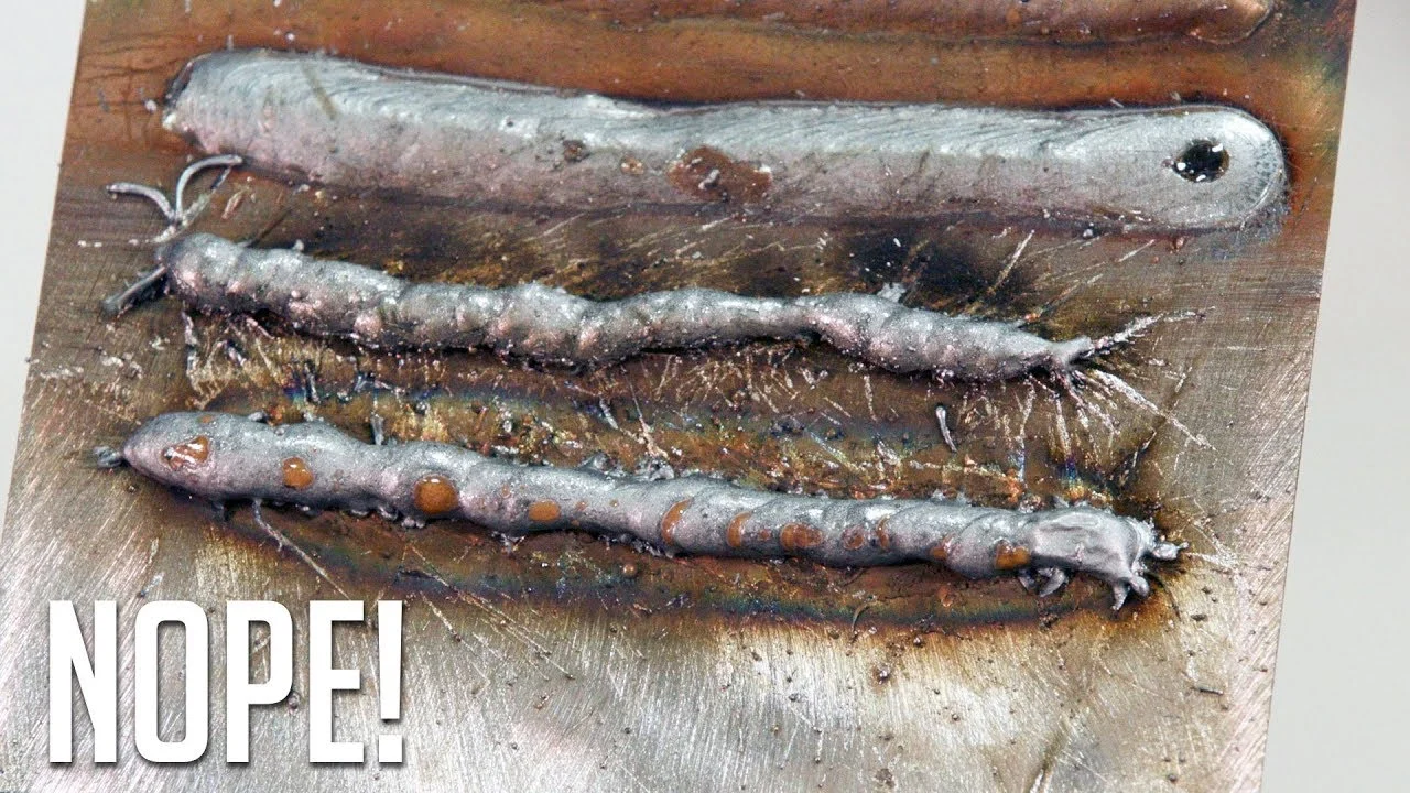
Inspect the bead and the surrounding base metal after it cools Look for cracks crater defects undercut overlap porosity excessive spatter incomplete fusion and inconsistent width If a.
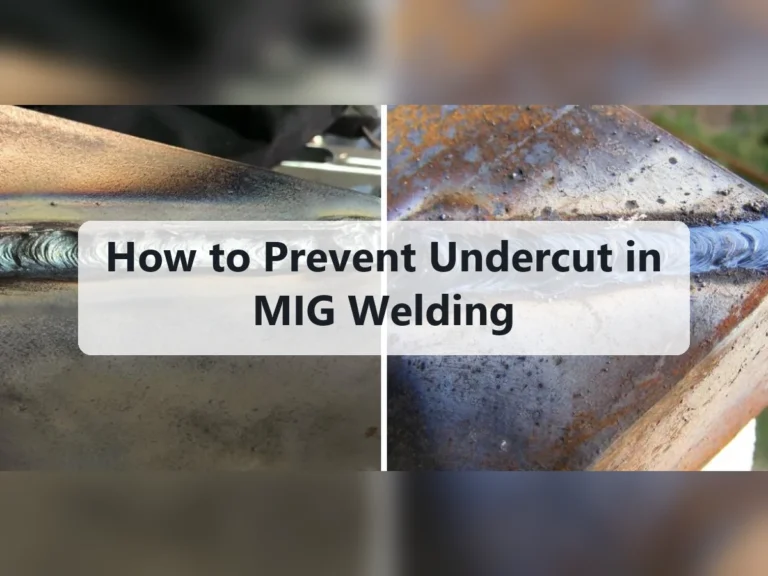
- Undercut: A groove at the toe can result from excessive heat, high travel speed, or poor angle control.
- Overlap: Metal rolls onto the base without fusing, often because travel is too slow or the puddle is too large.
- Crater cracking: Stopping abruptly can leave a depression that cools and cracks.
- Incomplete fusion: A bead may sit on top of the joint when heat, cleaning, angle, or travel control is inadequate.
Why covering a bad bead fails
Adding another bead over visible defects does not automatically restore strength Slag from contamination trapped gas lack of.
When practical, grind or otherwise remove defective weld metal to sound material, clean the area, and reassess the settings and joint. For regulated or critical work, follow the specified inspection and repair requirements.
Safety Mistakes That Make Welding More Dangerous
Good technique cannot compensate for unsafe preparation. MIG welding creates intense light, heat, sparks, fumes, electric shock hazards, and fire risk. Personal protective equipment is necessary, but it is only one layer of protection.
Wear a properly rated welding helmet flame-resistant clothing welding gloves sturdy footwear and suitable eye protection for grinding Keep combustible materials away from sparks provide appropriate ventilation or.
- Ventilation first: Do not weld in a confined or poorly ventilated space without a controls-based plan suitable for the hazard.
- Protect nearby people: Use screens and ensure others do not view the arc without proper eye protection.
- Manage cylinders: Secure gas cylinders upright, protect valves, and keep them away from heat and impact.
- Inspect after welding: Check for smoldering materials and hot metal before leaving the area.
Welding over unknown coatings
Paint plating oil and galvanized coatings can produce hazardous fumes when heated Cleaning the visible surface does not necessarily eliminate the hazard throughout the material Identify the coating.
Ignoring electrical and fire hazards
Do not weld with damaged cables, exposed conductors, wet gloves, or wet clothing. Keep the work lead and gun cable positioned to avoid damage, and disconnect power before servicing internal components unless the equipment instructions specifically require otherwise.
A fire watch may be appropriate when sparks can travel into hidden spaces or nearby combustibles. Welding on containers, tanks, or previously used vessels requires specialized evaluation; residual contents or vapors can ignite or explode.
Troubleshooting Common MIG Welding Symptoms
When a weld goes wrong record what the arc did instead of changing every control at once Note.
The exact correction depends on the machine and process, but symptom-based checks provide a logical starting point. Make one change, test on scrap or an extension of the same joint, and inspect the result before changing another variable.
| Symptom | Likely causes | First checks |
|---|---|---|
| Excessive spatter | Unbalanced voltage and wire speed, wrong polarity, contamination, poor ground | Confirm polarity, clean the joint, inspect the ground, then fine-tune settings |
| Porosity or pinholes | Wind, gas leak, blocked nozzle, dirty metal, moisture | Check gas delivery and coverage, clean the nozzle and base metal |
| Wire burns back to tip | Wire speed too low, stickout too short, worn tip, feeding resistance | Inspect tip and liner, verify feeding, then adjust wire speed |
| Cold, tall bead | Travel too fast, low heat, long stickout, poor joint access | Reduce stickout, check settings, and direct the arc into both sides |
| Burn-through | Too much heat, slow travel, excessive gap, thin material | Improve fit-up and reduce heat input with controlled short welds |
A practical diagnostic order
- Stop and make the work area safe before inspecting the equipment.
- Confirm the wire type, diameter, polarity, gas, and machine mode.
- Inspect the ground, contact tip, liner, drive rolls, nozzle, and cable connections.
- Clean the joint and check fit-up, gap, coating, and moisture.
- Verify gas flow and protect the arc from drafts.
- Test on similar scrap, changing one setting or technique factor at a time.
- Examine the bead and determine whether the repair requires removing defective metal.
Frequently Asked Questions About Common MIG Welding Mistakes
Why does my MIG weld look good but remain weak?
A smooth surface can conceal incomplete fusion, shallow penetration, porosity, or an unmelted joint edge. Check whether the arc was directed into the joint, whether the metal was clean, and whether travel speed and heat were suitable.
For important work, use the inspection method required for the application rather than relying only on appearance. A cosmetic bead is not proof of structural quality.
Should I increase wire speed to get deeper penetration?
Not automatically. Wire speed increases deposition and is related to amperage, but penetration also depends on voltage, polarity, travel speed, stickout, joint design, and arc placement.
Start with a suitable wire-and-voltage combination, then make controlled adjustments. Excessive wire speed can cause stubbing and a tall, poorly fused bead instead of better penetration.
What causes popping and spattering during MIG welding?
Popping commonly indicates an unstable arc. Possible causes include an imbalance between wire speed and voltage, poor grounding, wrong polarity, contaminated metal, incorrect stickout, feeding resistance, or inadequate gas coverage.
Check the simplest physical causes first: clean the joint, verify the ground and polarity, inspect the contact tip and liner, and confirm the wire feeds smoothly.
Can I MIG weld rusty or painted steel?
Welding over rust, paint, oil, or scale can create porosity, poor fusion, excess spatter, and hazardous fumes. Prepare the joint to sound metal whenever the material and procedure allow it.
Coated materials require additional hazard controls. In particular, do not treat galvanized or unknown coatings as ordinary bare steel.
Why is my weld bead narrow and raised?
A narrow, raised bead can result from traveling too quickly, using insufficient heat, holding excessive stickout, or directing the arc away from the joint. The bead may not wet the sidewalls adequately.
Check the puddle and arc location, shorten stickout, and compare settings with the appropriate chart. Avoid slowing dramatically if the joint is thin; that may cause burn-through instead.
Is a push angle or pull angle better for MIG welding?
A slight push angle often provides a clear view and suitable shielding for solid-wire MIG, while a pull angle may change bead shape and penetration. The best choice depends on the joint, position, wire, gas, and procedure.
Consistency matters more than choosing an extreme angle. Keep the nozzle close enough for coverage and direct the arc into the joint rather than merely along its surface.
When should I grind out a MIG weld and start over?
Remove and reassess a weld when it has cracks, obvious lack of fusion, serious porosity, burn-through, incorrect placement, or another defect that could affect the joint. Covering a defective bead may trap the problem underneath.
For critical or regulated work, use the specified repair and inspection procedure. If you cannot determine whether the weld is sound, do not assume it is safe because it looks smooth.
Conclusion
The reliable way to avoid MIG failures is to control the entire process prepare clean metal confirm polarity and consumables establish a solid ground and gas shield balance.
Understanding how not to weld most common mig welding mistakes also means recognizing limits No setting can replace safe ventilation correct joint design suitable inspection or qualified procedures.
Before your next weld, make a short pre-weld check for polarity, ground, wire,