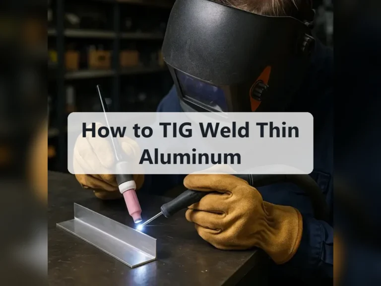
How to Set a TIG Welder for Aluminum: Beginner Setup Guide Tips
Aluminum can look simple to weld, yet it exposes weak TIG settings quickly. The metal conducts heat away from the joint, its oxide layer melts at a much higher temperature than the aluminum underneath, and the bright puddle can make it difficult to judge progress. A setup that works well on steel may produce a dirty, unstable arc on aluminum.
Learning how to set a TIG welder for aluminum is manageable when you treat the job as a sequence of controlled choices rather than a single amperage adjustment. You need the right current type, shielding gas, tungsten, preparation, and starting range for the thickness of the workpiece.
This guide explains those choices for a beginner using an AC-capable TIG machine. You will prepare the joint, connect the torch and work lead, select practical starting settings, tune the arc while watching the puddle, and inspect a short test bead before welding the actual part. Always give priority to your machine manual when its limits or controls differ.
At a glance
- Use AC with 100% argon for ordinary aluminum TIG welding.
- Clean the oxide layer mechanically without embedding steel or dirt in the joint.
- Judge settings by arc stability, puddle behavior, bead appearance, and the absence of contamination.
How to set a TIG welder for aluminum
Use this method for common aluminum sheet, plate, and tubing with a conventional AC TIG welder. The exact amperage depends on thickness, joint design, fit-up, alloy, torch cooling, and whether you are welding with a foot pedal or torch-mounted control, so the settings below are starting points rather than guarantees.
Tools you will need
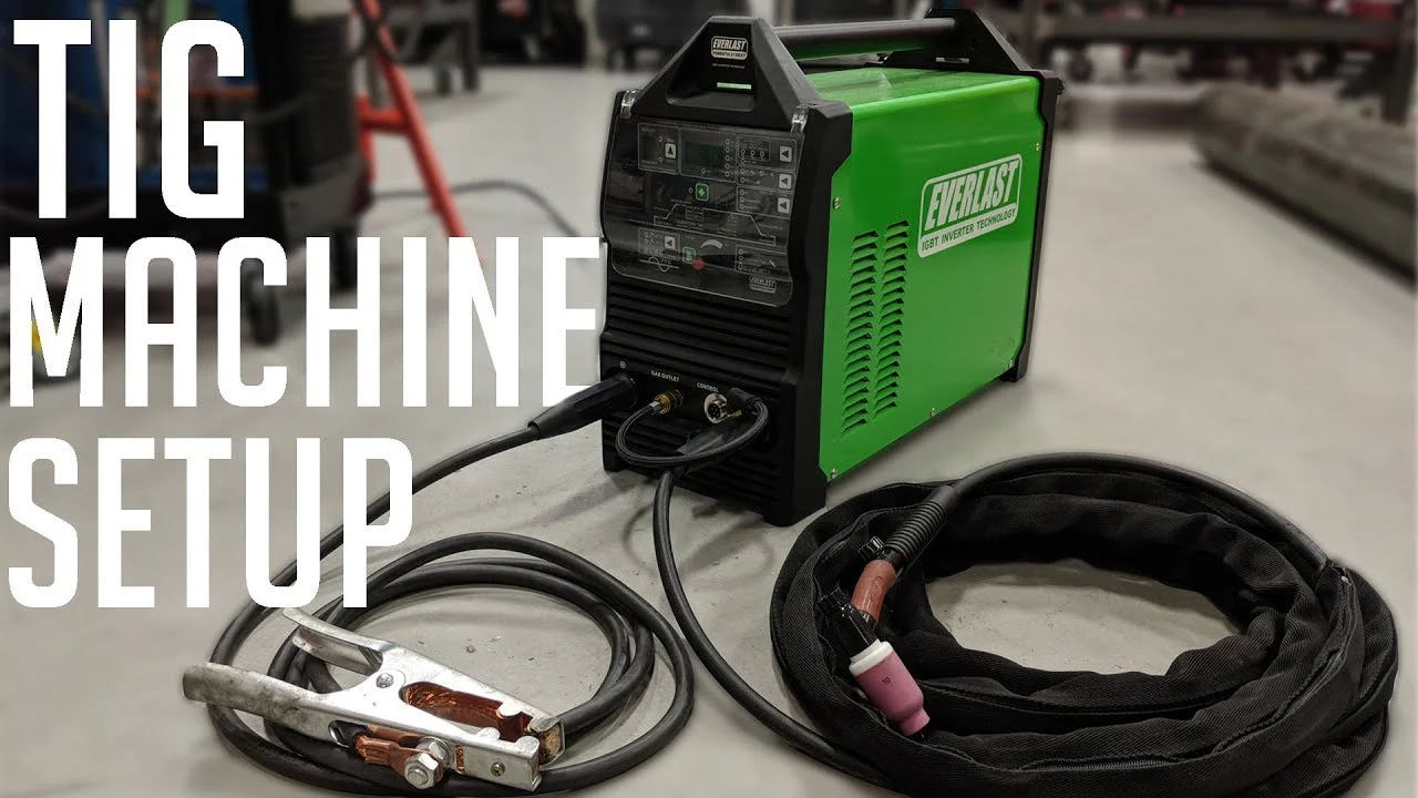
- AC-capable TIG welder with a torch, work clamp, and amperage control
- 100% argon cylinder, regulator, and suitable gas hose
- Appropriate tungsten electrode and ceramic gas cup
- Stainless-steel brush used only for aluminum cleaning
- Acetone or another manufacturer-approved degreaser and clean, lint-free cloths
- Matching aluminum filler rod, if the joint requires filler
- Auto-darkening welding helmet, TIG gloves, flame-resistant clothing, and safety boots
- Optional: scrap aluminum of the same alloy and thickness for test welds
Step 1 Confirm the machine and workpiece are suitable
Check that the welder provides AC output, not only DC. AC alternates between electrode-negative and electrode-positive portions of the cycle; this lets the arc heat the workpiece while helping disrupt aluminum oxide. A DC-only TIG machine is generally not the right tool for ordinary aluminum work.
Read the welder manual for its duty cycle, maximum output, gas connection, tungsten diameter range, and control terminology. Inspect the aluminum for paint, anodizing, oil, moisture, and coatings. Do not weld unknown coated material until you know how the coating behaves when heated, because fumes and residues can create a serious hazard.
Step 2 Prepare the joint and remove contamination
Cut and fit the parts so the joint is close and even. A large gap forces you to add more heat and filler, while a dirty or poorly aligned joint can make a correct electrical setup appear defective.
Remove grease with a clean cloth and suitable degreaser, then let the surface dry completely. Use a dedicated stainless-steel brush to scrub the joint immediately before welding. The brush should not have been used on carbon steel, because embedded iron particles can contaminate the aluminum.
For thick material, remove heavy oxide and sharp edges as appropriate for the joint design. Avoid aggressive grinding that leaves abrasive grit in the seam. Keep cleaned parts covered and handle them with clean gloves; fingerprints can add oil that later causes porosity.
Important
Wear a helmet with the correct lens shade, gloves, and flame-resistant clothing, and provide ventilation. TIG arc radiation can injure unprotected eyes and skin, while heated aluminum, filler, cleaning chemicals, and shielding gas all create separate hazards. Stop if you cannot identify the material or control fumes safely.
Step 3 Install the tungsten and choose the torch setup
Start with a 2% lanthanated tungsten for a versatile aluminum setup. A 2.4 mm (3/32-inch) electrode suits many general-purpose jobs, while a smaller diameter is useful at lower amperage and a larger one is appropriate for higher current when the torch and machine support it. Follow the electrode manufacturer’s recommendations if they differ.
Grind the tungsten lengthwise to a clean point or small truncated point using a dedicated wheel. A pointed electrode gives a focused arc, but aluminum AC can round the tip during operation. That slight rounding is normal; a large, misshapen ball, repeated arc wandering, or tungsten particles in the puddle indicate that the electrode is overheating, contaminated, or being used with unsuitable settings.
Fit a ceramic cup large enough to provide dependable gas coverage. A standard cup is usually adequate for a sheltered joint; a larger cup or gas lens can help when the joint requires more coverage, but it may need a different collet body and screen. Set the electrode extension conservatively, typically only as far out as the cup and joint access require.
Step 4 Connect argon, work lead, and torch controls
Secure the argon cylinder upright, connect the regulator, and check that the hose and fittings are rated for shielding gas. Set the machine to the gas type specified for TIG aluminum: 100% argon is the normal starting choice. Do not substitute an argon-carbon dioxide or oxygen mix used for some MIG applications.
Connect the torch and work clamp according to the machine’s labeled TIG terminals. Inspect the clamp jaws and attach it to clean metal on the workpiece or table. A poor return path can cause a weak or erratic arc, so do not rely on a painted, rusty, or heavily oxidized connection.
Set preflow and postflow if your machine provides them. Preflow allows shielding gas to replace air before the arc starts; postflow continues protection while the hot tungsten and weld solidify. If the manual gives no starting value, use a modest preflow and enough postflow to keep the tungsten from discoloring, then adjust after observing the result.
Step 5 Select AC, initial amperage, and arc controls
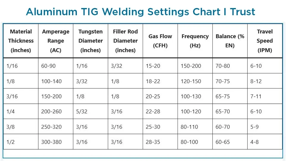
Choose AC TIG mode and disable unnecessary pulsing until the basic arc is stable. Set maximum amperage according to the thickness and joint, then use the foot pedal or torch control to approach the heat you need. A useful starting estimate for many aluminum joints is roughly 1 amp per 0.001 inch of thickness, but joint design, heat sinking, alloy, and machine behavior can move the practical setting substantially.
A useful way to approach how to set a tig welder for aluminum is to check your progress after each stage.
For example, thin sheet may need a low maximum with careful pedal control, while a thick butt joint may need substantially more capacity and preheating practices permitted by the material and procedure. Do not treat an amperage chart as a substitute for a test weld. The correct setting is the one that forms a controlled puddle without excessive melting, burn-through, or sluggish fusion.
Set AC frequency near the machine’s middle range as a starting point. Higher frequency generally makes the arc narrower and more focused; lower frequency can make it broader and softer. Set AC balance near the manufacturer’s recommended middle setting, often with more electrode-negative time than electrode-positive time.
More electrode-positive time can increase oxide cleaning but also heats the tungsten and reduces available penetration.
If your machine displays balance as electrode-negative percentage, a common starting range is around 65 to 75 percent electrode negative. If it displays cleaning percentage or electrode-positive percentage, the number may look reversed. Confirm the meaning in the manual before changing it.
Step 6 Set gas flow and perform a controlled test
Begin with the flow rate recommended for your cup, torch, and shop conditions; many general aluminum TIG setups start in the neighborhood of 15 to 20 cubic feet per hour. Excessive flow is not automatically better. It can create turbulence that draws room air into the shielding zone, while too little flow allows gray, sooty, or porous welds.
Place the tungsten over clean scrap of the same or similar thickness. Start the arc without touching the tungsten to the work, and use the pedal or torch control gradually. Watch for a stable arc, a bright but controlled puddle, and a surface that becomes wet without instantly collapsing or spreading far beyond the joint.
On aluminum, the oxide-cleaning action may appear as a narrow frosted or shiny zone around the puddle. A small amount can be normal. A very wide etched area, a rapidly balling tungsten, or a harsh arc suggests that the balance, amperage, gas coverage, or electrode setup needs attention.
Check your result
A sound test begins easily, stays centered, and produces a clean puddle without persistent popping. The tungsten remains intact, the gas continues after you stop, and the test bead is metallic rather than covered with black residue or scattered pinholes.
Step 7 Tune the arc and weld a short test bead
Adjust one control at a time so you can connect each change with its result. If the arc is broad and wandering, try a slightly higher AC frequency or check tungsten shape and arc length. If the tungsten overheats or contaminates, reduce excessive cleaning time, check the polarity and balance display, shorten the arc, and verify that postflow is adequate.
Keep the arc short and consistent, generally close to the diameter of the tungsten when joint access allows. Hold the torch near 70 to 80 degrees from the work and angle it only slightly in the direction of travel. Add filler at the leading edge of the puddle rather than dipping the rod into the arc, and keep the rod inside the argon envelope as much as possible.
Travel steadily after the puddle wets both sides of the joint. Aluminum often starts cold and then becomes fluid quickly as heat accumulates, so use the pedal to reduce heat or move faster near the end. A short test bead should have even width, smooth tie-in at both edges, and no obvious soot, craters, or holes before you proceed to the actual part.
Step 8 Weld the joint, finish the crater, and let it cool
Position the parts so you can maintain torch angle, arc length, and filler placement without reaching awkwardly. Tack the joint as needed, then clean any oxide or residue exposed by tacking. Start with enough amperage to establish fusion, and control the puddle rather than holding maximum current continuously.
Feed filler consistently if the joint needs reinforcement or has a gap. If the puddle becomes too wide or the edges begin to sag, release some pedal pressure or increase travel speed. If the puddle will not wet both sides, check fit-up and cleanliness before simply turning the current higher.
At the end, taper the current gradually with the pedal or downslope control instead of abruptly breaking the arc. Keep the torch over the cooling crater until postflow ends. This reduces crater cracking and protects the hot tungsten from oxygen.
Let the part cool naturally unless the material procedure calls for a different treatment.
What the aluminum TIG controls actually change
The machine controls are related, but they do not solve the same problem. Understanding their effects makes troubleshooting more logical and helps you avoid changing several settings at once. Understanding how to set a tig welder for aluminum also means recognizing the limits of the method.
AC polarity and oxide cleaning
In AC TIG, the electrode-negative portion concentrates more useful heat in the workpiece and generally supports penetration. The electrode-positive portion helps break up aluminum oxide but places more heat into the tungsten. The balance control changes how much time the arc spends in each portion.
Use enough cleaning action to handle the oxide condition, not the maximum cleaning value by default. Clean base metal and a dedicated brush reduce the amount of electrical cleaning required. Excessive cleaning can make the tungsten run hot, reduce penetration, and create an unnecessarily wide etched zone.
Amperage, frequency, and arc length
Amperage controls how much heat is available, although actual heat also depends on travel speed and how long the arc dwells over the joint. A foot pedal is useful because aluminum can absorb heat quickly at first and then become fluid as the workpiece warms.
AC frequency changes the shape and feel of the arc. A higher setting can improve control on a narrow joint, while a lower setting can spread heat over a wider area. Arc length matters just as much: a long arc spreads the heat and weakens shielding, while a short arc is more concentrated but requires steadier hand control.
Shielding gas and tungsten size
Argon protects the molten aluminum and tungsten from oxygen and nitrogen in the surrounding air. It does not replace cleaning, and it cannot compensate for a draft, damaged hose, loose fitting, or excessive torch angle that exposes the puddle.
Tungsten diameter should match the current range and torch capacity. A very small electrode overloaded with heat may deform or shed particles; an oversized electrode at low current can make arc starting and control less convenient. Keep the tungsten clean and regrind it if it touches the filler or molten puddle.
How to check the finished weld
Verification begins with appearance but should not end there. A clean-looking aluminum bead can still lack fusion, contain porosity, or have a weak crater, so inspect the joint under good light after it has cooled.
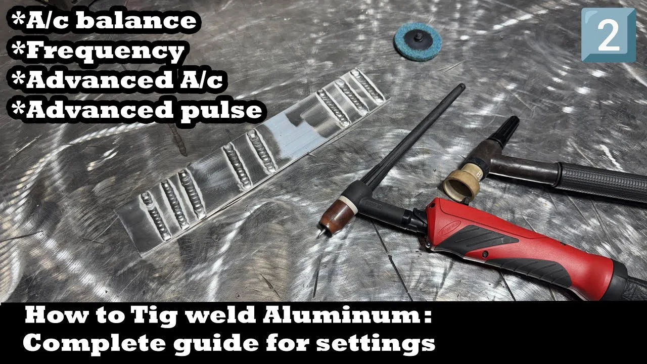
- Look for an even bead that ties into both sides without a sharp groove along the edges.
- Check for pinholes, dark specks, black soot, cracking, or a rough, sugar-like surface.
- Look for a reasonable cleaning zone rather than a very broad etched band.
- Confirm that the crater is filled and does not show a star-shaped crack.
- For a noncritical practice coupon, examine the reverse side for evidence of penetration where the joint design calls for it.
- For a load-bearing, pressure-containing, safety-critical, or code-controlled part, use the specified inspection and qualification process rather than relying on appearance.
If the bead is sound on scrap but poor on the actual part, compare thickness, alloy, joint fit-up, heat sinking, surface preparation, and torch access. The problem may not be the machine setting. When a weld must carry a safety-critical load or seal pressure, stop and obtain a qualified welding procedure or competent inspection instead of guessing at settings.
Troubleshoot the most common aluminum TIG problems
Make one change at a time and repeat a short test. The table below points to likely causes, but inspect the simple physical causes first: cleanliness, gas leaks, return connection, tungsten condition, and arc length.
| What you see | Likely causes and response |
|---|---|
| Black soot or a dirty gray bead | Insufficient shielding, a draft, contaminated surface, dirty filler, or an overly long arc. Check gas flow and leaks, clean again, shorten the arc, and keep filler in the gas coverage. |
| Porosity or pinholes | Oil, moisture, oxide, poor gas coverage, turbulent excessive flow, or a contaminated tungsten. Reclean the joint, inspect the hose and cup, correct the flow, and regrind the electrode. |
| Tungsten balls excessively or becomes unstable | Too much electrode-positive cleaning, excessive current for the electrode, wrong polarity, poor postflow, or contact with the puddle. Verify AC settings and reduce the load on the tungsten. |
| Puddle will not wet the joint | Low amperage, a cold heavy heat sink, oxide, poor fit-up, or a long arc. Improve preparation and control, then increase heat only as needed. |
| Edges burn away or the sheet collapses | Too much heat, slow travel, a large gap, or excessive dwell. Reduce pedal input, move sooner, improve fit-up, or use a suitable backing and joint design. |
| Arc wanders or starts poorly | Damaged tungsten, an inconsistent grind, an excessive arc length, poor work connection, or unsuitable electrode size. Regrind, tighten the return connection, and check the torch setup. |
When to change balance rather than amperage
If the joint is clean but the tungsten is overheating and the etched area is broad, review AC balance before raising or lowering amperage. Too much electrode-positive time can create those symptoms. If the oxide layer remains visibly disruptive after proper mechanical cleaning, a modest increase in cleaning action may help, but watch the tungsten closely.
When gas flow is the wrong fix
Increasing flow does not always improve shielding. A high flow rate can produce turbulent coverage, especially with a large cup or in a draft, and turbulence can pull air into the arc. Move the work away from fans, repair leaks, use an appropriate cup, and return to a moderate manufacturer-recommended flow before making further changes.
Beginner FAQs about TIG welding aluminum
These answers cover common setup decisions that cause confusion when the first test weld does not look right.
Can I TIG weld aluminum with DC?
Ordinary aluminum TIG welding is normally done with AC because AC provides a balance between workpiece heating and oxide disruption. Some specialized processes use DC with unusual techniques or equipment, but a beginner should use an AC-capable machine and follow its manual.
Is pure argon required for aluminum TIG?
100% argon is the standard shielding gas for most aluminum TIG work. Helium or argon-helium blends may be used for specialized high-heat applications, but they require different settings and are not the simplest starting point.
Should I use pure tungsten for aluminum?
Pure tungsten was traditionally associated with aluminum AC, especially older transformer machines. Modern inverter machines commonly use lanthanated tungsten for reliable starting and general-purpose operation. Follow the electrode and welder manufacturer’s guidance rather than assuming one tungsten type suits every machine.
Why does my aluminum puddle suddenly get too large?
Aluminum accumulates heat as you travel, so the puddle can grow even when your hand speed stays constant. Reduce pedal pressure, increase travel speed, use appropriate tacks, and avoid dwelling in one area. Excessive amperage, a large gap, or a thin edge can make the change happen faster.
How do I know whether the aluminum is clean enough?
After degreasing and brushing with a dedicated stainless-steel brush, the joint should be free of visible oil, paint, loose oxide, and brush debris. Clean immediately before welding and avoid touching the prepared area. If contamination continues to appear, inspect the filler, gloves, table, and cleaning cloths.
Set up, test, and refine your aluminum TIG weld
Learning how to set a TIG welder for aluminum starts with AC, pure argon, a clean joint, a suitable tungsten, and moderate control settings. From there, use a scrap test to judge the arc and puddle instead of chasing a single universal amperage or balance number.
Make adjustments in small, deliberate changes: correct contamination and gas coverage first, then tune amperage, AC balance, frequency, arc length, and travel speed. When the test bead is stable, clean, and properly fused, repeat the setup on the actual joint while managing the heat buildup. For structural, pressure, or otherwise safety-critical work, use an appropriate qualified procedure and inspection rather than relying on a visual beginner check alone.