How to MIG Weld Tubing: Instructions, Tips, and Useful Advice
To MIG weld tubing, clean and fit the joint, select the correct wire, gas, polarity, and settings, then weld with controlled travel speed and heat.
An unexpected problem with tubing welds is that a bead can look smooth while the joint has little useful penetration. Excessive heat may also distort thin tubing, pull a frame out of square, or burn through a wall before the welder notices.
Learning how to mig weld tubing means understanding the signs that separate a harmless cosmetic irregularity from a structural or leak-causing defect This guide explains material preparation joint.
- ✓Clean metal, tight fit-up, correct polarity, and adequate shielding gas matter as much as amperage.
- ✓Short-circuit MIG is usually the practical choice for thin and medium-wall steel tubing.
- ✓Tack in stages and alternate sides to control distortion before completing the weld.
- ✓A smooth appearance does not prove strength; inspect fusion, penetration, alignment, and defects.
How to MIG Weld Tubing
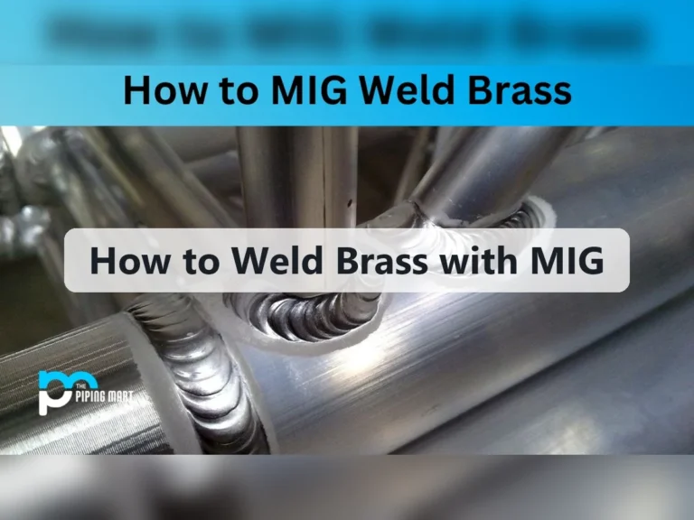
MIG welding tubing is a process of joining hollow sections without damaging their shape or compromising the surrounding wall The most common application is mild-steel square rectangular or.
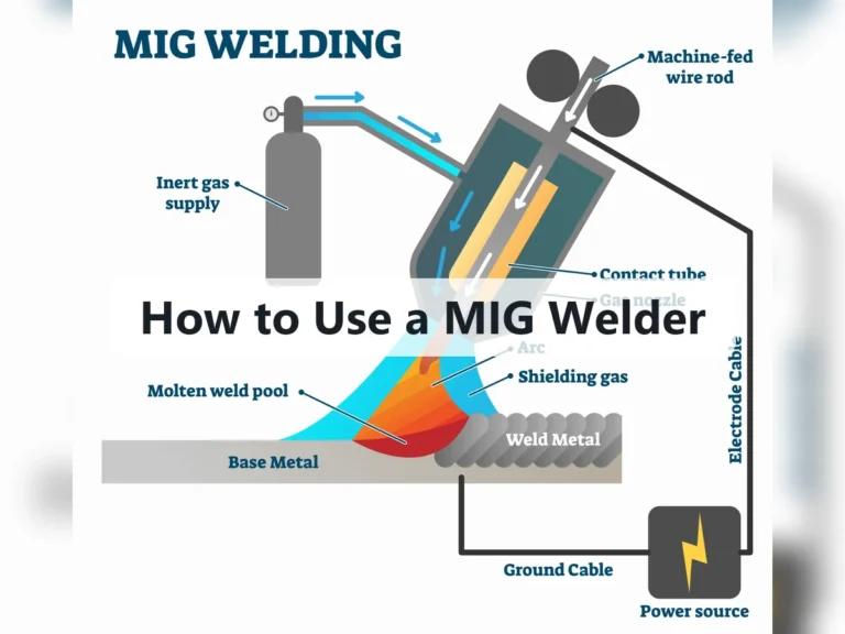
For ordinary mild steel a wire-feed welder using solid ER70S-6 wire and a shielding gas blend containing argon and carbon dioxide is a common setup A gasless flux-cored.
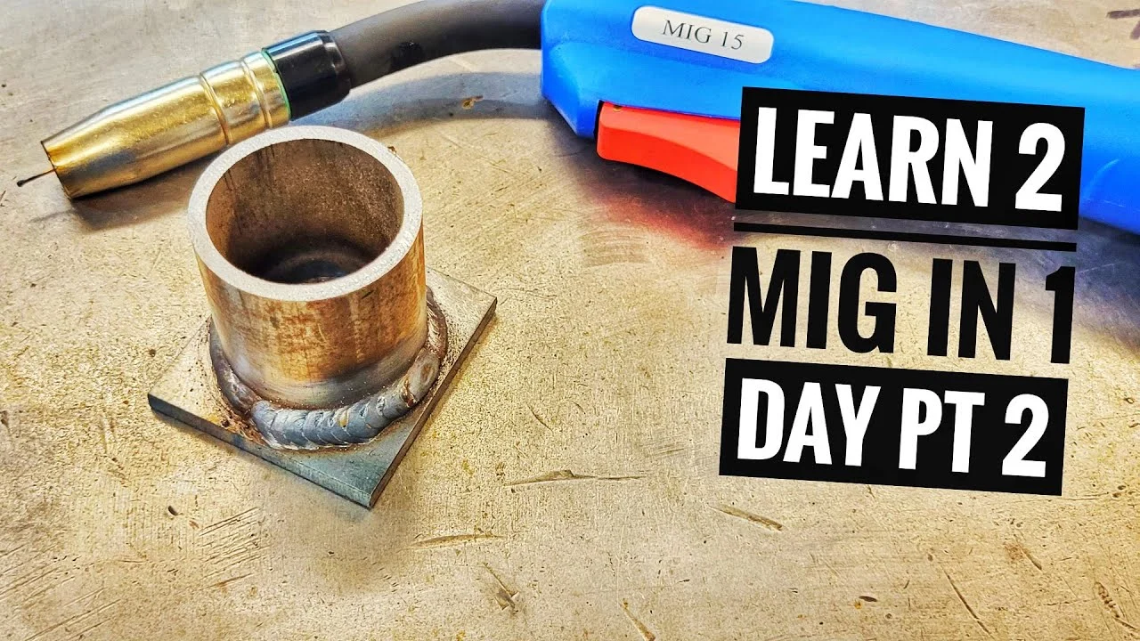
- Material: Confirm whether the tubing is mild steel, stainless steel, aluminum, galvanized steel, or an unknown alloy before choosing wire and gas.
- Wall thickness: Thin tubing needs lower heat and shorter welds; thick-wall tubing needs enough energy for sidewall fusion.
- Joint purpose: A decorative brace and a load-bearing frame should not automatically receive the same joint design or inspection standard.
- Working position: Flat welding is easiest, while vertical and overhead work require lower fluidity and tighter control.
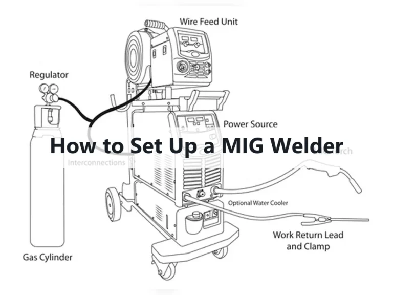
Before striking an arc read the welder s operating instructions and identify its output range duty cycle wire size options and gas requirements A small 120-volt machine may.
Choose the joint before choosing the settings
A square butt joint joins two ends edge to edge while a lap tee or corner joint places one tube against another Tubing often has a thin wall.
For thin-wall tubing, a close-fitting joint with a small, consistent gap is generally easier to control than a wide opening. Thicker tubing may benefit from beveling the edges when full penetration is required, but beveling reduces the remaining wall and can increase burn-through risk if done too aggressively.
Materials, Tools, and Safe Preparation
Good welds begin before the machine is turned on. Tubing may carry mill scale, oil, paint, rust, moisture, galvanizing, or cutting residue. Contamination can cause porosity and unstable arc behavior, while coatings can release hazardous fumes when heated.
Use a grinder wire brush or suitable abrasive to clean the weld zone until bright uncontaminated metal is exposed Clean both sides of the joint where practical not.
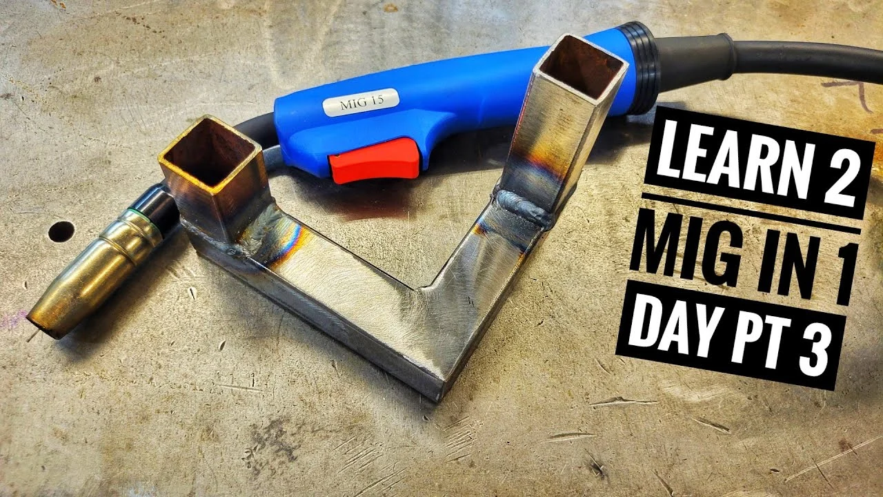
- Protect your eyes and skin: Wear a properly rated welding helmet, flame-resistant clothing, gloves, closed footwear, and hearing protection when grinding.
- Control fumes: Use local exhaust or effective ventilation, especially when welding painted, oily, galvanized, or unknown tubing.
- Prevent fire: Clear combustible materials, inspect the opposite side of the tubing, and keep a suitable fire extinguisher accessible.
- Ground correctly: Clamp the work lead to clean metal close to the weld, not to a painted stand or a distant component.
Helpful equipment includes clamps, magnetic squares, a steel rule, a combination square, a scribe, a center punch, a grinder, a wire brush, and a chipping or slag tool when using flux-cored wire. A temperature crayon or infrared thermometer can help with repeatable work, although surface temperature readings are not a substitute for procedure control.
Special concerns with galvanized and coated tubing
Galvanized tubing has a zinc coating that can produce dangerous fumes when heated Do not simply weld over it as though it were clean steel Remove the coating.
Painted or powder-coated tubing presents similar contamination and fire concerns. Strip the coating around the joint and inspect the far side for hidden combustible material. If the coating cannot be safely removed or the material is of unknown composition, stop and obtain qualified guidance rather than guessing.
Check fit-up and alignment
Clamp the parts so the joint remains in the intended position during tacking Measure diagonals on rectangular assemblies to check squareness and use a straightedge to detect twist.
A gap that changes around the joint is difficult to weld consistently. Correct the cut, use a thin shim only when appropriate, or adjust the joint before welding. Do not rely on a large weld bead to fill poor preparation; extra filler can conceal lack of fusion and create more distortion.
MIG Welder Setup for Tubing
The machine must be configured as a complete system: wire type and diameter, polarity, shielding gas, gas flow, voltage, wire-feed speed, contact-tip condition, and gun technique all interact. Start with the chart supplied with the welder or wire, then make controlled adjustments on a piece of matching scrap tubing. This distinction matters when answering “how to mig weld tubing”.
For common mild-steel tubing solid wire in a small diameter is often easier to control on thin walls Larger wire can deposit more metal but generally demands more.
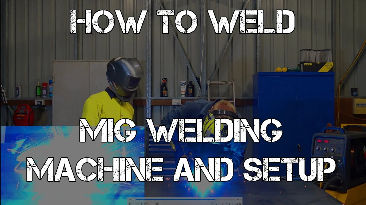
- Polarity: Solid MIG wire normally uses electrode-positive polarity; verify the correct connection for the specific wire and process.
- Gas flow: Set flow according to the gun, nozzle, and environment; excessive flow can create turbulence and draw air into the shield.
- Stickout: Keep a consistent contact-tip-to-work distance appropriate to the wire and transfer mode.
- Test coupon: Adjust on the same tubing thickness and joint style rather than relying only on a generic chart.
Voltage mainly influences arc length and bead profile while wire-feed speed strongly affects amperage in a conventional constant-voltage MIG machine Increasing wire speed without balancing voltage can make.
| Condition | Likely adjustment direction | What to observe |
|---|---|---|
| Wire stubs into the puddle | Reduce wire speed or increase voltage slightly | Arc should remain continuous rather than pushing the gun away |
| Excessive spatter and a long arc | Reduce voltage or correct wire-speed balance | Transfer should sound and feel more controlled |
| Bead sits high and narrow | Increase heat modestly or slow travel | Edges should wet into both sides without melting the wall |
| Burn-through on thin wall | Lower heat, increase travel, or use intermittent welding | Back side should remain intact and aligned |
The familiar “bacon” sound is only a rough clue, not a quality test. Arc sound changes with gas, wire, position, machine design, and joint geometry. Watch the puddle: it should wet both edges, remain manageable, and leave a bead that is neither sharply crowned nor deeply gouged at its toes.
Why scrap testing matters
Make a test joint from offcuts of the same tubing. Use the same cleaning method, joint gap, position, wire, gas, and machine leads that will be used on the actual assembly. This reveals whether the selected settings cause burn-through or lack of fusion before the finished part is at risk.
After cooling inspect the test visually and where appropriate cut or bend a sample to evaluate fusion A bead that looks acceptable from above can have an unfused.
Step-by-Step Technique for Tubing
Once the parts are clean, aligned, and clamped, the welding sequence becomes the main defense against distortion. Tubing heats quickly because its wall is often thin, and a long bead on one side can pull a frame out of square. The objective is to distribute heat while maintaining fusion.
Hold the gun so the nozzle provides adequate shielding without dragging through the joint. A modest work angle and a consistent travel angle are easier to control than a sharply tilted gun. Keep the wire aimed where the two pieces meet, not toward one edge unless the joint design specifically requires that bias.
- Tack widely: Place tacks at several locations around the assembly before adding connecting welds.
- Check twice: Re-measure diagonals and straightness after tacking because parts can move as soon as the clamps are released.
- Use short welds: Stitching or alternating sections often controls heat better than one uninterrupted pass.
- Watch the puddle: Guide by the molten pool and its edge wetting, not solely by the changing color of the bead behind it.
- Position the assembly: Whenever possible, rotate the work so the joint is flat or close to flat. Avoid awkward reach that changes gun distance during the weld.
- Make initial tacks: Place small, sound tacks at opposite sides or corners. Allow enough cooling to keep the joint from shifting.
- Recheck geometry: Measure squareness, length, diagonals, and twist. Correct movement before filling between the tacks.
- Complete in balanced sections: Weld a short section, move to an opposing area, and repeat. This spreads heat and reduces directional pull.
- Clean as required: Remove spatter and slag between passes when using flux-cored wire. Inspect each section before covering it.
- Finish and cool naturally: Let the part cool in still air unless a qualified procedure specifies otherwise. Avoid quenching a hot joint with water.
Travel speed, angle, and work position
If travel is too slow the puddle becomes large the tubing wall overheats and the bead may sag or burn through If travel is too fast the bead.
A slight push angle often gives a broad visible puddle and reduced penetration which can be useful on thin tubing A slight drag angle can concentrate heat more.
Flat-position welding is the most forgiving. In vertical-up work, reduce the puddle size, use controlled pauses at the edges, and avoid excessive heat. Vertical-down travel can be faster on thin material in some applications, but it may provide less penetration and is not automatically appropriate for a load-bearing joint.
How to manage corners and ends
Outside corners shed heat quickly at first, then can melt abruptly as the surrounding area warms. Start with a stable tack and avoid lingering at the corner. On a tee or lap joint, aim for equal fusion into both members instead of directing the arc entirely at the thicker section.
At the end of a bead, pause only long enough to fill the crater without enlarging the hole. A crater left unfilled can become a crack-starting notch or a leak path. If the machine has crater-fill or run-in features, test them on scrap before using them on the actual tubing.
Troubleshooting MIG Welds on Tubing
When a weld fails, separate appearance problems from structural problems. Spatter may be inconvenient but superficial, whereas lack of fusion, cracks, severe undercut, and burn-through can make a joint unreliable. Do not grind a defect smooth and assume it has been repaired; remove the defective metal, correct the cause, and weld again when appropriate.
Keep these limitations in mind when considering “how to mig weld tubing”.
Inspection should begin after the joint has cooled enough to handle safely. Look at bead continuity, toe fusion, crater termination, porosity, cracking, distortion, and the opposite side of thin tubing. A bright light and a clean surface make small discontinuities easier to see.
- Porosity: Often linked to contamination, leaks, inadequate shielding, excessive gas flow, wind, or a blocked nozzle.
- Burn-through: Usually caused by too much heat, a large gap, slow travel, or lingering at one location.
- Lack of fusion: May result from low heat, fast travel, poor aim, mill scale, or a joint edge hidden by an oversized bead.
- Undercut: Commonly associated with excessive voltage, high travel speed, long arc length, or too much heat at the toes.
| Defect or symptom | Possible causes | Corrective action |
|---|---|---|
| Pinholes or scattered pores | Dirty steel, damp wire, gas turbulence, wind, leaks | Clean again, check hoses and nozzle, shield the area, and verify flow |
| Thin wall has a hole | Heat too high, travel too slow, gap too wide | Use lower heat, shorter stitches, tighter fit-up, and let sections cool |
| Bead appears on top without side fusion | Travel too fast, low heat, incorrect gun aim, scale | Clean, slow slightly, adjust settings, and direct the arc into the joint |
| Assembly pulls out of square | Long welds, uneven sequence, insufficient tacking | Re-align if possible and use balanced, intermittent welding |
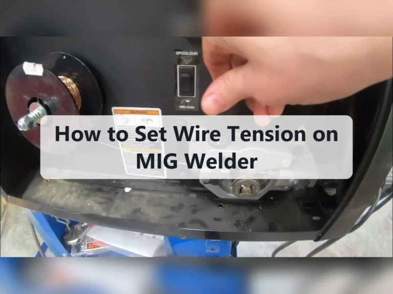
| Wire feeds irregularly | Incorrect tension, liner restriction, worn tip, poor spool setup | Inspect the feed path, replace damaged consumables, and set tension correctly |
Porosity and shielding problems
Porosity appears as small holes or pinpoints in the bead and may be visible only after grinding. Check for oil, moisture, paint, or mill scale first. Then inspect the gas cylinder, regulator, hose, connections, nozzle, diffuser, and contact tip.
A nozzle packed with spatter can disturb shielding even when the flowmeter appears normal.
Outdoor wind can displace shielding gas surprisingly easily. Use a windbreak that does not create a hazardous enclosed fume area. Increasing gas flow is not always the solution; excessive flow can become turbulent and pull surrounding air into the arc.
Burn-through and lack of penetration
Burn-through is a hole or severe collapse in the tubing wall Reduce heat input by lowering voltage or wire speed as appropriate increasing travel speed using smaller wire.
Lack of penetration is different from burn-through the weld may remain intact on the surface while failing to reach the required depth Improve cleaning and joint preparation verify.
Quality Checks, Repairs, and Project Limits
After welding remove spatter and slag without gouging the base metal Grinding can improve appearance but excessive grinding reduces the effective section and may expose or create defects.
Check that the assembly remains straight and square. Inspect both sides of accessible joints, especially the inside of corners and the back side of thin-wall tube. For a frame or support, verify that welds do not interfere with fasteners, moving parts, drainage, or later access for inspection.
- Continuity: Confirm that the weld reaches the intended length without unexplained gaps or crater cracks.
- Fusion: Look for smooth transition into both members, with no visible cold lap or unfused edge.
- Profile: Reject severe undercut, excessive convexity, sharp notches, or a bead that obscures the joint.
- Geometry: Recheck dimensions, diagonals, twist, and fit with mating parts after cooling.
When a weld should be repaired
Repair a joint when it contains cracks significant porosity burn-through incomplete fusion severe undercut or an incorrect weld length that affects its purpose Mark the defect remove it.
For a small noncritical project visual inspection may be enough to identify obvious problems Structural repairs vehicle components pressure-containing tubing lifting devices railings subject to code requirements and safety-critical assemblies may require qualified design approved procedures or non-destructive examination MIG welding skill.
Corrosion protection and long-term care
Uncoated steel tubing can rust quickly at welds because cleaning removes protective mill scale and heat changes the surface Remove residue allow the part to dry and apply.
Inspect outdoor frames and frequently loaded assemblies periodically. Look for rust bleeding from a seam, new cracking, distortion, coating failure, or a joint that has begun to flex. Stop using a component if a crack or major deformation appears until the cause and repair have been evaluated.
FAQ: How to MIG Weld Tubing
What wire is best for MIG welding mild-steel tubing?
Solid ER70S-6 wire is a common choice for clean or properly prepared mild steel because it contains deoxidizers that tolerate small amounts of surface scale better than some alternatives. Select the diameter based on wall thickness and the welder’s supported range.
Flux-cored wire can be useful outdoors or when greater penetration is needed, but it requires the correct polarity, technique, and cleanup. Always match the wire to the machine setup and the material.
What gas should I use for MIG welding tubing?
A commonly used shielding gas for mild-steel tubing is an argon-carbon-dioxide blend, which generally provides a stable arc and manageable spatter. Pure carbon dioxide is also used, but it often produces a harsher arc and more spatter.
Stainless steel and aluminum require different wire and gas choices. Do not use a mild-steel setup by default on those materials.
Should I weld tubing continuously or in short sections?
Short, alternating sections are usually safer for thin tubing and assemblies that must remain square. Continuous welding can add unnecessary heat and pull the joint out of alignment, especially on long corners or frames.
Use enough weld length for the joint’s purpose. Short welds are not automatically adequate simply because they reduce distortion; strength, design, and service loads still determine the required weld size and length.
How do I prevent burn-through on thin-wall tubing?
Use a tight, consistent fit-up, lower the heat, keep the gun moving, and avoid pausing in one place. Tack first, allow brief cooling intervals, and alternate sides or corners to distribute heat.
Practice on matching scrap. If the wall is extremely thin, a different process, smaller wire, pulse capability, or a qualified fabrication procedure may provide better control than basic short-circuit MIG.
Can I MIG weld rusty or painted tubing?
You should remove rust, paint, oil, and loose scale from the weld area before welding. Contamination can cause porosity, spatter, unstable arc behavior, and weak fusion.
Paint and coatings can also produce hazardous fumes or ignite. Galvanized tubing requires particular caution because heating zinc produces hazardous fumes; remove the coating safely and provide effective ventilation.
Why does my tubing weld look good but fail?
A smooth bead can still have lack of fusion, shallow penetration, hidden porosity, or an incorrect weld size. Visual appearance is only one part of inspection, especially when the joint carries a load.
Review the test coupon, joint preparation, settings, and bead placement. For safety-critical or regulated work, use an appropriate qualified procedure and inspection method instead of relying on appearance alone.
Conclusion
Successful tubing work comes from controlling the entire process identify the material clean the joint fit and clamp the parts accurately set the machine from a real test.
Inspect the finished joint rather than judging it only by shine or bead shape. Wear proper protection, control fumes and fire hazards, and obtain qualified engineering or welding guidance when the tubing is structural, pressure-related, vehicle-critical, or otherwise safety-sensitive.
Cut two matching tubing scraps, clean and fit them like the real project, and use that test joint to tune settings before welding the finished assembly.
The answer to “how to mig weld tubing” should be applied with these conditions and limitations in mind.