How to Prevent Undercut in MIG Welding: Step-by-Step Instructions
Prevent undercut by using the correct voltage, amperage, wire speed, travel speed, and gun angle while keeping the arc and weld puddle properly controlled.
Undercut is a groove melted into the base metal along one or both edges of a weld that the filler metal does not adequately fill. It weakens the joint by reducing the effective thickness of the parent material and can become a crack-starting point under vibration, impact, or repeated loading.
So what should you change when a sound-looking MIG bead leaves a sharp channel beside the weld This guide explains how to prevent undercut in MIG welding by.
- ✓Reduce excessive heat and avoid outrunning the weld puddle; voltage, wire feed speed, and travel speed must work together.
- ✓Keep the gun angle, contact-tip-to-work distance, and arc length consistent instead of correcting defects with random machine changes.
- ✓Use clean metal, suitable joint fit-up, correct shielding gas flow, and enough filler deposition for the joint.
- ✓Inspect both weld toes for continuous grooves, then verify that corrections do not create lack of fusion, excess spatter, or burn-through.
What Undercut Looks Like and Why It Matters
Undercut appears as a narrow depression at the weld toe, where the bead meets the base metal. The groove may be continuous or intermittent, and it can occur on one side when the gun favors that edge or on both sides when the overall settings and travel technique are wrong.
A healthy fillet or groove weld should transition smoothly from the base metal into the weld face A sharp line or channel beside the bead indicates that the.
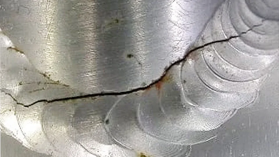
- Weld toes: Look for a groove running parallel to either edge rather than assuming every dark line is undercut.
- Groove depth: A shallow visual depression may be cosmetic, while a measurable groove can reduce section thickness and require repair.
- Continuity: Intermittent undercut often points to inconsistent travel speed, gun angle, or hand position.
- Joint type: Fillet welds, outside corners, and thin edges are more sensitive to puddle control than broad, flat joints.
Undercut is different from lack of fusion which means the weld metal did not properly bond to the sidewall or previous bead It is also different from overlap.
Before changing the machine clean the weld and inspect it from several angles A wire brush adequate lighting and a small inspection gauge can reveal whether the edge.
How to Prevent Undercut in MIG Welding: Control the Main Causes
The most reliable approach is to treat undercut as a process-control problem. Begin with the least disruptive correction, make one change at a time, and deposit a short test bead on comparable material before returning to the production joint.
There is no universal machine setting that eliminates undercut on every MIG weld. Material thickness, wire diameter, polarity, joint position, shielding gas, transfer mode, and joint design all affect the result. The settings printed on a machine or wire package are a starting range, not a substitute for observing the puddle.
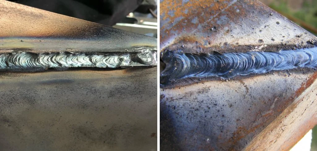
- Heat balance: Excessive voltage or amperage can wash away the edges before enough filler metal arrives.
- Travel control: Moving too quickly leaves a narrow bead and lets the arc dig into the toes.
- Puddle placement: Direct the arc so the molten metal reaches both sidewalls instead of favoring one edge.
- Stable setup: Correct polarity, clean contact equipment, reliable shielding, and consistent stickout support predictable arc behavior.
Reduce excessive voltage or arc length
Excessive voltage generally lengthens the arc and spreads the heat over a wider area. Depending on the transfer mode and material, it can produce a broad, flat bead with melted edges that are not filled quickly enough. The result may be undercut, excessive spatter, or an unstable arc.
Lower voltage slightly and run another short bead while watching the puddle The arc should be smooth and the bead should have a controlled profile rather than a.
Match wire feed speed and amperage
On many constant-voltage MIG systems wire feed speed primarily controls amperage and deposition rate If the wire feed is too low for the selected voltage and travel speed.
Make small adjustments rather than turning both controls sharply. A useful test is to hold the gun at a consistent position and change only wire feed speed, then compare the bead width, penetration, spatter, and weld-toe shape. The objective is enough deposition to fill the joint without creating excessive reinforcement or burn-through.
Slow the travel speed without lingering
Traveling too quickly is one of the most common causes of undercut. The arc spends less time melting and filling each section of the joint, so the bead becomes narrow and the toes may remain gouged. A modest reduction in speed often lets the puddle wet both edges.
Slowing down does not mean stopping at the toes or making a very wide overheated bead Move at a steady pace that keeps the puddle behind the arc.
Use a controlled work and travel angle
For a typical fillet weld, a work angle near the joint bisector helps distribute heat and filler metal between both members. A travel angle commonly kept near a modest push or drag position can support visibility and shielding, but the best choice depends on position, transfer mode, joint access, and equipment. This distinction matters when answering “how to prevent undercut in mig welding”.
An extreme angle directs the arc toward one sidewall and can undercut the favored edge. It may also reduce shielding effectiveness or make the puddle appear smaller than it really is. Keep the gun steady, avoid wrist rotation, and position your body so the torch can travel smoothly through the complete weld.
Maintain a consistent contact-tip-to-work distance
Contact-tip-to-work distance, often called stickout, affects the electrical resistance of the wire and the arc’s behavior. Excessive stickout can preheat the wire, reduce effective arc energy, and make the bead irregular. Very short stickout can increase heat at the tip, create contact problems, and make it difficult to see or control the puddle.
Keep the distance consistent with the wire, transfer mode, and procedure being used. Do not compensate for a long stickout by randomly increasing machine output. First bring the gun to a repeatable position, then fine-tune the machine while observing the bead.
Prepare the Joint Before Striking the Arc
Good settings cannot fully compensate for poor preparation. Mill scale, rust, paint, oil, moisture, and heavy oxidation interfere with arc stability and wetting. They can make the puddle appear sluggish, encourage spatter, and prevent the molten metal from flowing smoothly into the base-metal edges.
Clean the joint and the surrounding area with a suitable mechanical method and remove contaminants that could produce harmful fumes Confirm that the work clamp has a clean.

- Edge condition: Remove burrs and sharp irregularities that can distort the puddle or imitate a groove.
- Root opening: An excessive gap may require a different current range, travel strategy, or joint sequence.
- Alignment: Mismatched members change the effective work angle and can make one toe easier to undercut.
- Restraint: Clamps and tack welds should hold the joint without preventing the planned weld sequence from controlling distortion.
Check joint fit-up and edge thickness
Thin edges lose heat quickly but can also melt away rapidly when exposed to a concentrated arc A sharp outside corner may need careful positioning so the arc.
Correct the fit-up before attempting to solve every problem with torch movement. If the joint is too tight, penetration and sidewall fusion may suffer. If it is too open, the puddle may sag or require additional passes.
The correct preparation depends on the material, thickness, joint design, and applicable welding procedure.
Choose wire and shielding gas deliberately
The wire diameter and composition should match the material and weld size. A wire that deposits too little metal for the travel speed may leave the toes underfilled; a wire that is too large for the joint can make control difficult. Use the recommended polarity for the wire and process.
Shielding gas also affects arc characteristics penetration bead profile and spatter A gas mixture that produces a softer more controllable arc may behave differently from one that produces.
Excessive gas flow can create turbulence and draw surrounding air into the shield. Drafts can do the same. Shield the work area from wind, but do not enclose a welding area without maintaining safe ventilation and following the requirements for the space.
Use Gun Movement That Fills Both Weld Toes
Gun manipulation should support the puddle rather than replace correct settings Many operators focus on the bright arc and move too quickly to follow it while the weld.
A slight controlled weave may help distribute metal in a wider joint but a large weave can lengthen the time the arc spends at each sidewall and increase heat input On.
- Pause with purpose: If using a weave, pause briefly at each toe only long enough to let the puddle wash in, then cross the center smoothly.
- Keep the arc visible: Excessive gun angle or stickout can hide the edge you need to monitor.
- Support your hands: A stable forearm and comfortable body position reduce sudden speed changes.
- Practice the motion: Dry-run the gun along the joint before welding so the travel path is predictable.
Push, drag, and travel-angle considerations
A pushing technique generally gives a clearer view of the joint and can produce a flatter, wider bead with appropriate settings. A dragging technique can increase penetration or produce a different bead profile, depending on the process and material. Neither approach is a universal cure for undercut.
Keep these limitations in mind when considering “how to prevent undercut in mig welding”.
If the arc is directed too far ahead of the puddle it may melt the leading edges without depositing enough metal behind them If it is directed too.
Control starts and stops
Undercut often appears at the beginning or end of a weld where the operator accelerates releases the trigger abruptly or fails to fill the crater Begin on sound.
Do not whip the gun away while the puddle is still molten. A sudden withdrawal can leave a crater, crater cracking, or a sharp underfilled termination. For repair work, remove the defective area and blend the restart into sound metal rather than simply placing another bead over an uncorrected groove.
Set Up and Tune the MIG Welder Systematically
Randomly turning voltage, wire speed, and inductance can make a defect harder to diagnose. Use a repeatable sequence: verify the process and polarity, confirm wire and gas, inspect the consumables, prepare a test coupon, and then make one controlled adjustment at a time.
Listen to the arc and observe the wire transfer, but do not use sound alone as proof of quality. A smooth crackle can still produce undercut, lack of fusion, or an unacceptable profile if the gun is poorly positioned. Visual inspection of the bead and confirmation of the joint’s intended penetration remain essential.
- Polarity: Confirm the connections match the wire and welding process.
- Consumables: Check the liner, drive rolls, contact tip, diffuser, nozzle, and wire path for wear or contamination.
- Gas delivery: Verify cylinder supply, regulator operation, hose integrity, flow, and wind protection.
- Test coupon: Use similar thickness and joint geometry so the adjustment reflects the actual work.
A practical adjustment sequence
- Clean and fit the test joint, then position it as closely as possible to the production weld.
- Confirm wire diameter, shielding gas, polarity, and the machine’s basic recommended range.
- Set a comfortable stickout and gun angle, brace your hands, and make a short bead at a steady pace.
- Inspect both toes. If they are grooved, first moderate travel speed or heat rather than changing every control.
- Make a small voltage or wire-feed adjustment if the arc remains too forceful, too cold, or poorly matched.
- Repeat the test and compare bead width, toe transition, penetration, spatter, and puddle control.
Understand inductance and advanced controls
Inductance, arc dynamics, burnback, crater fill, and other controls vary by machine. They can influence arc softness, short-circuit behavior, spatter, and the way the puddle responds to changes in wire transfer. These controls should be adjusted only after the basic settings and technique are stable.
If the machine uses synergic or pulse programs, verify that the selected material, wire, gas, and diameter match the actual setup. A program can simplify tuning, but it cannot correct a poor work angle, excessive travel speed, dirty metal, or inadequate shielding. Record useful settings for repeat jobs instead of relying on memory.
Diagnose Undercut by the Weld’s Appearance
The location and shape of the groove can identify the likely cause. A groove on one side usually suggests torch angle, joint access, body position, or uneven heat distribution. Grooves on both sides more often suggest excessive heat, excessive arc length, fast travel, or insufficient deposition.
Use appearance as a starting clue, then verify the cause with a controlled test. A bead that looks smooth may still have inadequate fusion beneath the surface, while a visually rough bead may be sound after cleaning. When quality is critical, inspection methods and acceptance limits should be defined before welding begins.
- Both toes are grooved: Check heat, arc length, travel speed, and filler deposition.
- One toe is grooved: Recheck work angle, travel angle, access, and whether your hand is rotating.
- Groove at the finish: Review stopping technique, crater fill, and end-of-weld travel control.
- Groove with spatter: Investigate arc instability, poor gas coverage, dirty wire, or incorrect settings.
| Observed condition | Likely contributors | First correction to test |
|---|---|---|
| Long, narrow bead with undercut | Fast travel, low deposition, excessive arc length | Slow slightly, stabilize the arc, and confirm wire feed matches voltage |
| Wide, flat bead with sharp toes | Voltage or heat too high, puddle too fluid | Reduce voltage or heat modestly and reassess travel speed |
| Undercut on one side only | Incorrect work angle or torch favoring one member | Center the gun and keep the angle consistent through the joint |
| Undercut with poor penetration | Technique and settings are mismatched, or joint is contaminated | Clean the joint, verify polarity, and review the procedure range |
| Undercut at starts and stops | Sudden trigger movement or inadequate crater filling | Use a controlled start and finish, with tabs or crater-fill functions where suitable |
Correct Existing Undercut Safely
Do not assume a cover pass will hide or repair undercut. If the groove remains open, adding metal over it may trap an unfused edge or leave the original stress concentration beneath the new bead. The correct repair depends on the groove’s depth, length, location, material, joint design, and governing acceptance requirements.
For minor work clean the area thoroughly and evaluate whether the groove is within the permitted limit If it is not acceptable remove the defective metal by an.
- Expose sound metal: Remove contaminated, cracked, or visibly unfused material before depositing new weld metal.
- Blend carefully: Grinding should produce a smooth transition and should not gouge adjacent base metal.
- Reinspect: Clean the repair and check both toes, the start, the stop, and the surrounding heat-affected area.
- Escalate when needed: Critical or regulated work may require an approved repair procedure and qualified inspection.
Wear appropriate eye, face, hand, body, and respiratory protection for the task and control sparks, fumes, hot metal, and grinding debris. Never grind or weld on a container, coating, or unknown material without first addressing the hazards associated with it.
FAQ: Preventing Undercut in MIG Welding
Why does MIG welding create undercut?
MIG welding creates undercut when the arc melts the base-metal edge faster than the weld puddle fills it. Common causes include excessive voltage, excessive amperage, fast travel, long arc length, poor gun angle, insufficient wire deposition, and inadequate puddle control.
Should I slow down to stop undercut?
Often, yes. A modest reduction in travel speed gives the puddle more time to wet and fill both toes. Do not stop or linger excessively, because too much heat can cause burn-through, excessive reinforcement, distortion, or overlap.
Does increasing wire speed eliminate undercut?
It can help when the bead is underfilled because deposition is too low, but increasing wire speed is not a universal fix. If the voltage, stickout, travel speed, or gas setup is wrong, more wire may create spatter, an oversized puddle, or poor fusion.
Can too much voltage cause undercut?
Yes. Excessive voltage can lengthen and broaden the arc, melt the weld toes, and produce a flat bead that does not adequately fill the edges. Reduce it in small increments while preserving a stable arc and sufficient fusion.
What gun angle prevents undercut?
Use a controlled work angle that distributes heat and filler metal between the joint members, commonly near the joint’s centerline for a fillet weld. Keep the travel angle modest and consistent, because an extreme angle can direct the arc toward one toe.
Is undercut caused by too much shielding gas?
Shielding gas flow does not usually cause undercut by itself, but excessive flow can create turbulence and pull air into the shield. Drafts, leaks, a damaged nozzle, or an incorrect gas can also destabilize the arc and contribute to poor bead formation.
Can I weld over undercut without grinding?
Usually, you should not simply cover it. Clean and evaluate the groove first; if it exceeds the permitted limit, remove the defective area and blend it into sound metal before rewelding according to the applicable procedure.
Conclusion
Reliable results come from controlling the whole process rather than chasing one machine number. Clean and fit the joint, confirm the wire, polarity, and shielding, maintain a consistent gun position, and adjust heat, deposition, and travel speed in small steps. Inspect both toes and correct the underlying cause before accepting or repairing the weld.
When deciding how to prevent undercut in MIG welding, protect quality first: do not trade a visible groove for hidden lack of fusion, excessive heat, or an unsafe repair. For critical work, follow the applicable procedure and acceptance requirements and obtain the required inspection.
Make a short test bead on matching material, then change only one variable—travel speed, voltage, wire feed, or gun angle—until both weld toes transition smoothly without a groove.