How to Make a Good MIG Weld: Practical Steps and Helpful Tips
To make a good MIG weld, prepare clean metal, set the machine correctly, maintain a steady short arc, and control travel speed and gun angle.
A sound MIG weld begins before you pull the trigger. Clean base metal, proper joint fit-up, a suitable wire and gas combination, and safe equipment setup work together to determine whether the finished bead is strong, even, and properly fused.
The goal is not simply a weld that looks smooth A useful weld must join the parts without excessive spatter trapped contamination undercut porosity lack of fusion or distortion A shiny bead can still be weak if the heat travel speed or. This guide examines “how to make a good mig weld” and explains the details that matter in practice.
This guide explains how to make a good mig weld by connecting machine setup with real welding technique You will learn how to choose polarity and shielding gas.
- ✓Clean, tightly fitted metal and the correct polarity are foundations of reliable MIG welding.
- ✓Voltage controls arc length while wire-feed speed largely controls amperage, so adjust them as a pair.
- ✓A short, consistent arc and steady travel speed produce better fusion than trying to manipulate a wide bead.
- ✓Use test coupons to confirm settings before welding the actual project, especially on thin or critical material.
How to Make a Good MIG Weld
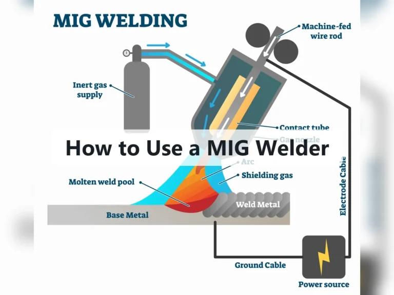
MIG welding technically called gas metal arc welding uses a continuously fed wire electrode and an electrical arc to melt the wire and the joint Shielding gas protects.
Before welding, identify the base metal, its thickness, the joint type, and the welding position. A butt joint on clean, flat mild steel may need a very different setup from a lap joint on thin sheet metal or a vertical fillet weld on thicker plate.
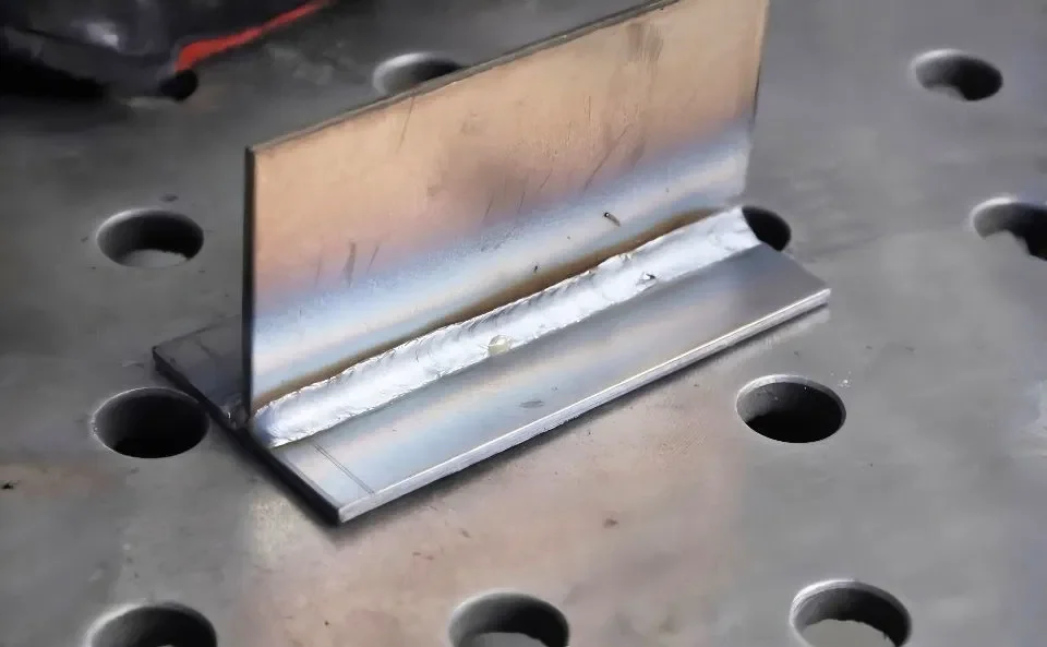
- Material: Confirm whether the work is mild steel, stainless steel, or aluminum; each requires compatible wire, gas, liner, and contact-tip choices.
- Thickness: Use the machine’s rated output and recommended wire size rather than forcing a small welder to make a heavy structural joint.
- Joint position: Flat welding is generally easier because gravity helps keep the molten pool controlled; vertical and overhead work require smaller puddles.
- Consumables: Match wire diameter, polarity, shielding gas, and contact tip to the wire manufacturer’s guidance.
Select the wire and shielding gas
For common mild-steel work solid ER70S-type wire with a mixed argon-and-carbon-dioxide shielding gas is a common choice A higher carbon-dioxide mixture can provide deeper penetration and a more.
Flux-cored wire is another option. Some flux-cored wires are designed for gas-shielded use, while self-shielded wires do not require an external gas cylinder. They have different polarity and technique requirements, so do not assume that a setting for solid wire will work for flux-cored wire.
Aluminum generally needs a spool gun or other reliable wire-feeding arrangement, a suitable aluminum wire, and argon shielding gas. Stainless steel requires compatible stainless wire and shielding choices. Avoid using a general-purpose mild-steel setup simply because the machine can produce an arc.
Confirm polarity, grounding, and gas flow
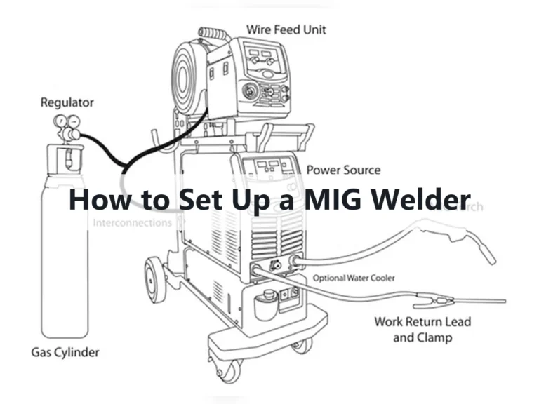
Most solid MIG wire applications use direct current electrode positive often shown as DCEP or reverse polarity Self-shielded flux-cored wire commonly uses a different polarity depending on the.
Attach the work clamp to clean metal as close to the weld as practical Paint rust mill scale and loose connections add resistance and can make the arc.
Shielding gas must reach the arc without being blown away. Set flow according to the equipment and gas setup, then protect the work area from drafts. Increasing flow excessively does not always improve shielding; turbulence can pull surrounding air into the gas envelope.
Prepare the Joint Before Striking an Arc
Joint preparation often determines weld quality more than a small change in machine settings. Remove oil, paint, heavy rust, moisture, and coatings from the weld area and from the surfaces where the work clamp connects. Contamination can create porosity, inclusions, unstable arc behavior, and weak fusion.
Fit the parts so the gap and alignment are consistent. A large or changing gap makes the puddle harder to control and may require more heat. A joint with no practical access for the arc can prevent proper sidewall fusion even when the bead appears attractive.
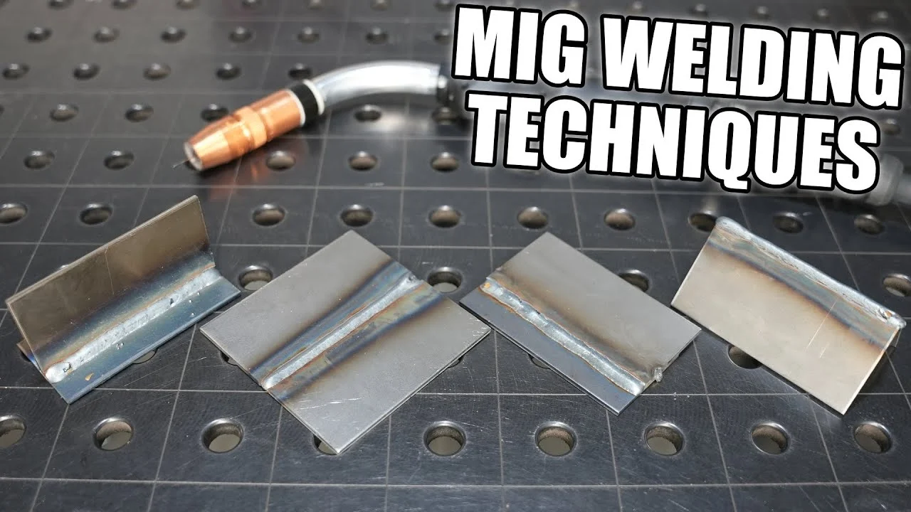
- Clean zone: Prepare the joint and a small area around it so dirt does not fall into the puddle or interfere with the clamp.
- Consistent gap: Keep the root opening uniform; excessive gaps increase burn-through risk on thin material.
- Secure parts: Clamp or tack the work so heat does not pull the joint out of alignment during welding.
- Access: Position the gun so the nozzle, contact tip, and wire can reach the joint without an awkward wrist angle.
Clean different metals appropriately
For mild steel remove loose scale with a wire brush or abrasive tool and degrease oily surfaces with a suitable cleaner Let the surface dry completely Do not.
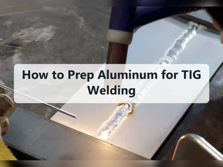
Aluminum develops an oxide layer that melts at a much higher temperature than the base metal Use tools reserved for aluminum to avoid embedding steel particles and clean.
Tack weld and plan the sequence
Place small, sound tacks at planned intervals rather than relying on one large tack that distorts the joint. Check alignment after each tack. If the parts move, correct the fit before continuing; welding over a misaligned joint usually makes the problem harder to fix.
For longer seams, alternate weld locations or use short sections when appropriate to distribute heat. The best sequence depends on the material, joint design, and distortion risk. Thin sheet may need brief stitches, while thicker plate may require a controlled continuous weld or multiple passes.
Set Voltage, Wire Speed, and Inductance Together
MIG controls can look simple, but voltage and wire-feed speed affect one another. In many machines, wire-feed speed largely determines amperage and deposition rate, while voltage influences arc length and bead profile. The exact control behavior varies by machine, especially with synergic or automatic programs.
This distinction matters when answering “how to make a good mig weld”.
Begin with the chart or settings supplied for your wire size material thickness gas and position Treat those numbers as a starting point not a guarantee Make a.
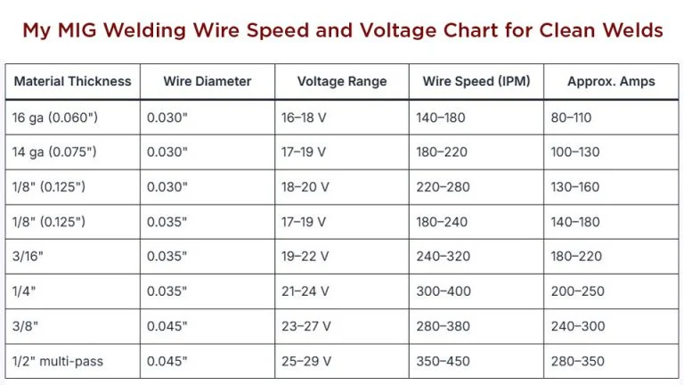
- Wire speed too high: The wire may push into the puddle, causing a harsh arc, stubbing, or excessive spatter.
- Wire speed too low: The arc can become long and erratic, with a tendency for the wire to burn back toward the contact tip.
- Voltage too high: The arc may become wide and unstable, increasing spatter, undercut, or a flat bead with poor control.
- Voltage too low: The wire may short aggressively, producing a narrow, tall bead and an unpleasant popping sound.
Use the test coupon as a calibration tool
Use scrap that closely matches the actual work in thickness joint type and position Make a short bead then inspect its width tie-in at both edges reinforcement spatter.
Change settings in small increments. If you change wire speed, voltage, travel speed, gun angle, and stickout simultaneously, you will not know which adjustment solved or created the problem. Record a useful setting for a recurring material and joint combination.
Understand inductance and advanced controls
Inductance arc control burnback and crater-fill controls vary by machine These features can influence how soft or forceful the arc feels how quickly current responds and how the.
Use the manufacturer’s recommended range before experimenting. A softer arc may help reduce spatter on certain short-circuit applications, while a more forceful arc may improve control in another setup. Make changes only after the basic voltage, wire speed, gas, and technique are working together.
Control the Gun, Arc, and Molten Puddle
Good MIG technique is primarily about keeping the arc and puddle predictable. Hold the gun comfortably, keep the nozzle at a consistent distance, and move at a speed that allows the edges of the joint to melt without letting the puddle grow too large.
For many short-circuit steel applications, a short arc and modest contact-tip-to-work distance are typical. Excessive stickout heats the wire before it reaches the arc and can reduce effective penetration. Excessive stickout also makes the arc less responsive and can encourage an inconsistent bead.
- Gun angle: Keep a modest work angle across the joint and a slight travel angle in the direction of movement unless the process guidance calls for something different.
- Travel speed: Move fast enough to prevent an oversized puddle, but slowly enough to fuse both sides of the joint.
- Stickout: Keep the wire extension consistent so the arc length and heating remain stable.
- Vision: Watch the leading edge of the puddle and both toes of the bead, not just the bright arc.
Push or drag?
With many solid-wire MIG applications a slight push angle can provide a broad visible puddle and a clean bead profile A slight drag angle can produce a more.
Avoid extreme angles. Pointing the gun too far ahead can reduce control of the puddle and may lead to shallow fusion. Dragging too steeply can trap slag when using flux-cored wire or create an excessively narrow, tall bead.
Use a straight bead before adding a weave
A controlled straight bead is often the best starting technique It reduces heat input and makes it easier to monitor travel speed puddle size and edge fusion Small.
If you must weave, pause only briefly at each side to melt the edges and move smoothly across the center. Do not use a weave to hide an unstable arc or an incorrect joint gap. Correct the underlying problem first.
Adapt the Method to Joint Type and Welding Position
The same machine settings do not work equally well in every position Gravity changes the shape of the molten pool and joint geometry changes how easily the arc.
Practice on the same joint orientation as the actual project. A bead that looks excellent on a horizontal coupon does not prove that the welder, settings, and technique are ready for an overhead or vertical joint.
- Flat: Keep the puddle controlled and avoid moving so slowly that excess heat creates a wide, concave, or distorted bead.
- Horizontal: Watch for the puddle sagging toward the lower side; a slight adjustment in angle and travel speed can improve sidewall control.
- Vertical: Use a smaller puddle, manage gravity, and follow the process guidance for upward or downward travel.
- Overhead: Limit puddle size and use appropriate settings and protective equipment; falling droplets and spatter increase the hazard.
Butt, lap, and fillet joints
For a butt joint, consistent alignment and gap are essential. Thin material may need a tight fit and short welds to prevent burn-through, while thicker material may require beveling or multiple passes for complete joint penetration.
In a lap joint direct the arc so both overlapping surfaces receive adequate heat A bead that sits mainly on the upper piece may look smooth but have. Keep these limitations in mind when considering “how to make a good mig weld”.
Thin sheet versus thick plate
Thin sheet metal is vulnerable to burn-through and distortion. Use the lowest practical heat input, maintain a tight fit, and consider short stitch welds with cooling time between them. Moving continuously without watching the puddle can turn a small hole into a larger damaged area.
Thicker plate may require higher deposition, preheating in some applications, joint beveling, and multiple passes. Do not assume that a large single bead is stronger. Inadequate penetration between passes, trapped slag from flux-cored work, or poor sidewall fusion can weaken a multi-pass joint.
Recognize Weld Defects and Correct the Cause
Inspection should include the bead surface and when practical the internal condition of the joint A good appearance is helpful but not conclusive Look for consistent width smooth.
When a defect appears, correct its cause instead of simply adding another layer. Grinding over a problem and covering it can conceal poor fusion or contamination rather than repairing the joint.
- Porosity: Check gas flow, leaks, drafts, nozzle blockage, dirty metal, damp consumables, and excessive stickout.
- Undercut: Reduce excessive voltage or travel speed problems, improve angle control, and avoid lingering at the wrong location.
- Lack of fusion: Check joint preparation, heat level, travel speed, gun position, and whether the arc reaches both surfaces.
- Burn-through: Reduce heat input, tighten the gap, increase travel speed, or use intermittent welds on thin material.
Spatter and an unstable arc
Some spatter is normal, but excessive spatter usually signals an unbalanced setup or inconsistent technique. Check polarity first, then confirm that the wire-feed speed and voltage suit one another. Dirty wire, a worn contact tip, poor grounding, and incorrect gas can also make the arc erratic.
Keep the nozzle free of accumulated spatter so gas can exit evenly. Replace a damaged or incorrectly sized contact tip. If the wire binds in the liner or drive rolls slip, the actual feed rate may fluctuate even when the control dial does not move.
Cracks, craters, and poor starts or stops
Cracks are a serious defect, not a cosmetic issue. Stop and determine whether the joint, material, contamination, cooling rate, restraint, or welding procedure is responsible. Do not assume that grinding out a visible crack and rewelding automatically resolves the underlying problem.
At the end of a weld abruptly releasing the trigger can leave a crater that becomes a weak starting point for a crack Use the machine s crater-fill.
Safety and Quality Checks Before You Weld
MIG welding produces intense ultraviolet radiation, heat, fumes, sparks, and electrical hazards. Wear a properly rated welding helmet with the correct shade, flame-resistant clothing that covers exposed skin, gloves, sturdy footwear, and suitable eye protection when grinding or cleaning.
Ventilation must control fumes without creating a draft that disrupts shielding gas Keep combustibles away from the work area inspect hoses and electrical leads secure gas cylinders upright.
- Fumes: Use local exhaust or effective ventilation and avoid breathing the plume, especially when coatings or unknown metals are present.
- Fire control: Remove combustible materials and keep suitable fire-control equipment available according to the workspace requirements.
- Gas cylinders: Secure cylinders, protect valves, and check connections for leaks using an appropriate method.
- Electrical condition: Keep cables, plugs, gun components, and the work clamp in sound condition and dry when required.
Inspect the finished weld
Allow the weld to cool enough for safe inspection, then remove spatter or slag as appropriate. Check both ends, the toes, the crater, and the transition into the base metal. Look for discontinuities that run across or along the bead rather than judging only its shine.
For a noncritical practice joint, a bend, break, or sectioned test can teach more than appearance alone. For load-bearing, safety-related, coded, or regulated work, use the required procedure and inspection method rather than treating a visual check as proof of structural adequacy.
Maintenance That Keeps MIG Welds Consistent
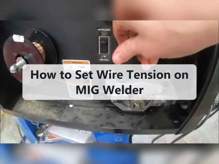
Even a well-chosen setup becomes unreliable when the equipment is neglected. Keep wire dry and clean, protect the spool from contamination, and make sure the drive-roll groove matches the wire type and diameter. Excessive drive-roll pressure can deform soft wire, while insufficient pressure can cause slipping.
Inspect the liner for restriction, replace worn contact tips, and clean the nozzle regularly. A contact tip that is loose, enlarged, or clogged can alter current transfer and cause burnback or arc instability. Keep the work clamp connection bright and tight.
- Before each job: Verify wire path, polarity, gas connection, ground contact, nozzle condition, and machine settings.
- During welding: Watch for changes in arc sound, wire feeding, gas coverage, and contact-tip temperature.
- After welding: Store consumables properly, remove spatter from the nozzle, and coil leads without sharp kinks.
Frequently Asked Questions About Making a Good MIG Weld
What does a good MIG weld look like?
A good weld is generally consistent in width and height, ties smoothly into both sides of the joint, and has no visible cracks, pinholes, severe undercut, crater defects, or excessive spatter. Appearance alone cannot confirm internal fusion or structural strength.
Why is my MIG weld bubbling or full of holes?
Bubbling and pinholes commonly indicate porosity. Check for gas leaks, drafts, an obstructed nozzle, insufficient or excessive gas flow, contaminated metal, damp consumables, and excessive wire stickout.
Should I push or pull a MIG weld?
A slight push is common with many solid-wire MIG applications, while a slight drag may suit certain flux-cored wires or joint conditions. Keep the angle modest and follow the wire’s process guidance; extreme angles can reduce control and fusion.
How far should the MIG gun be from the metal?
Maintain a consistent contact-tip-to-work distance appropriate for the wire and process. Excessive stickout can reduce penetration and destabilize the arc, while holding too close can increase burnback and damage the contact tip.
Why does my MIG weld have too much spatter?
Excessive spatter can result from mismatched voltage and wire speed, incorrect polarity, poor grounding, contaminated metal, incorrect gas, a worn contact tip, or an inconsistent gun position. Adjust one cause at a time and test on similar scrap.
Can I MIG weld rusty or painted metal?
Remove rust, paint, oil, and other contamination from the weld zone whenever possible. Welding over coatings can cause porosity and hazardous fumes, and unknown coatings should be treated as a safety concern rather than merely a surface problem.
How do I prevent burn-through on thin metal?
Use lower heat input, a controlled travel speed, a tight and consistent joint gap, and short stitch welds when suitable. Allow the material to cool between sections and practice on a matching coupon before welding the final part.
Conclusion
Learning how to make a good mig weld is a process of controlling the entire system clean and fit the joint match the wire and gas confirm polarity.
Remember that a visually attractive bead is not automatically a strong or safe weld. Use appropriate protective equipment, ventilation, and qualified procedures for critical work, and test your setup on comparable scrap before committing to the final joint.
Prepare a clean test coupon from the same material and thickness, make a short bead, and adjust only one setting or technique variable at a time until both appearance and fusion are consistent.