How to MIG Weld Thin Aluminum: Practical Steps and Helpful Tips
Use a spool gun or push-pull gun, 100% argon, aluminum wire, clean material, and short controlled welds to prevent burn-through.
Thin aluminum can be MIG welded successfully but it demands more control than mild steel because aluminum conducts heat quickly melts at a relatively low temperature and develops.
Learning how to mig weld thin aluminum is therefore less about simply turning down the amperage and more about balancing wire feeding, shielding gas, joint fit-up, travel speed, and heat management. A stable arc and clean preparation protect the finished panel from distortion, porosity, soot, and irregular bead shape.
This guide explains how to choose equipment and consumables prepare the aluminum set voltage and wire speed control the puddle and recognize common defects You will also learn.
- ✓Use a spool gun or push-pull system with soft aluminum wire, a U-groove liner, and pure argon shielding.
- ✓Clean aluminum mechanically and chemically, then weld soon after preparation to limit oxide and contamination.
- ✓Use short welds, skip around the joint, and let the work cool to control burn-through and distortion.
- ✓Set the machine from its aluminum chart, then fine-tune by listening to the arc and inspecting the bead.
- ✓Porosity, black residue, wire bird-nesting, and a collapsing puddle usually point to setup or heat-control problems.
How to MIG Weld Thin Aluminum
The first decision is whether the welder can feed aluminum wire reliably. Aluminum wire is soft and easily deformed, so a conventional steel setup with a long, tight torch liner often creates drag, bird-nesting, and inconsistent arc starts. For thin sheet, feeding problems can be more frustrating than the welding itself.
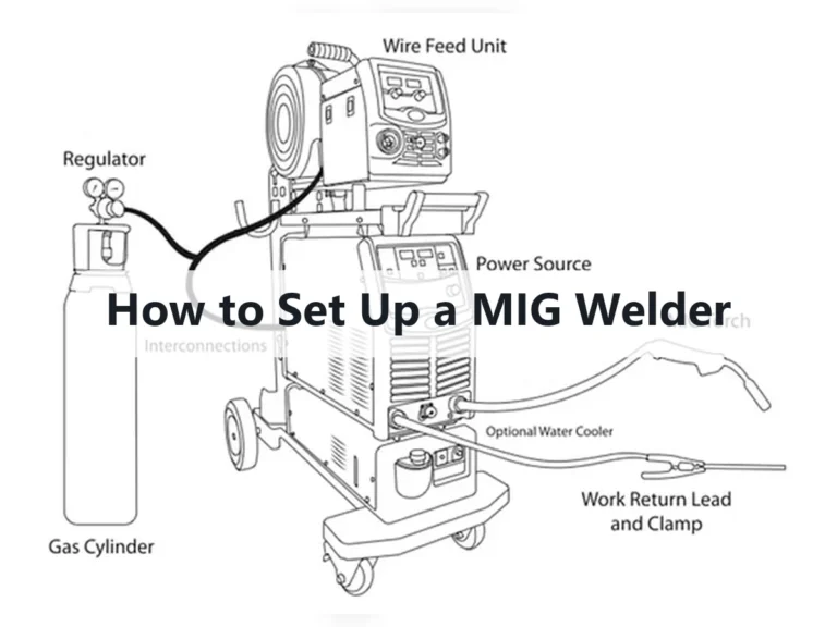
A spool gun places a small wire spool at the torch reducing the distance the soft wire must travel A push-pull gun uses a motor at both the.
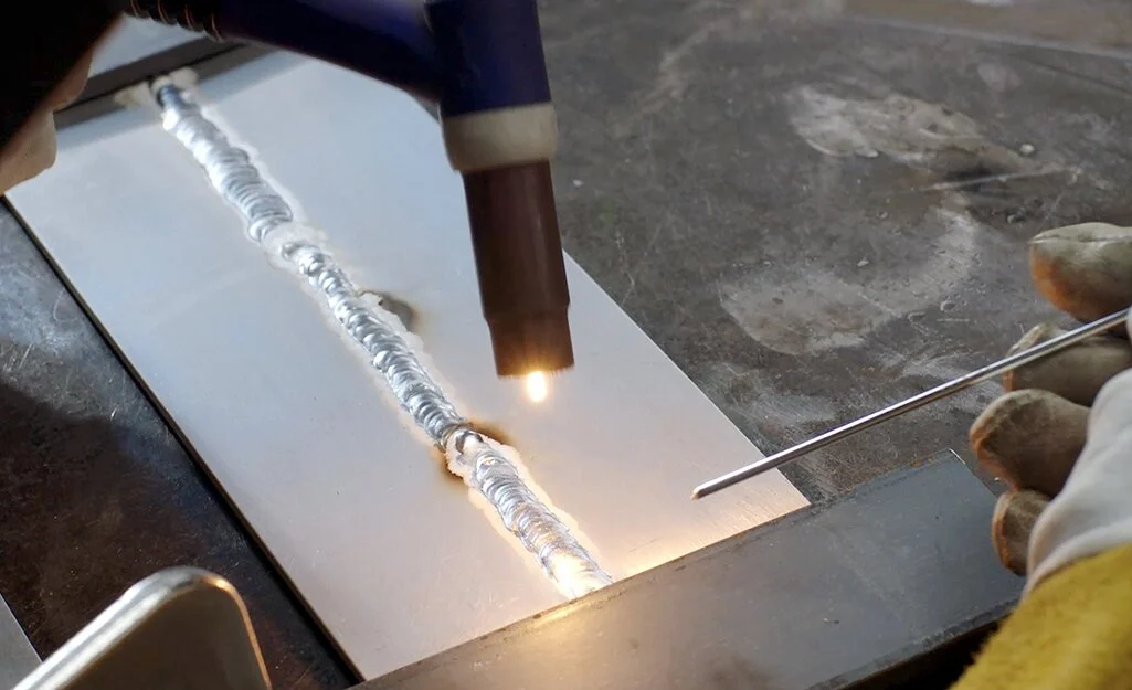
- Wire delivery: Choose a spool gun or push-pull gun whenever the machine supports one; it minimizes feeding resistance.
- Contact tip: Use a tip sized for aluminum wire and replace it if the bore is worn or the wire drags.
- Liner: Install a liner intended for aluminum, often a low-friction polymer or suitable dedicated liner.
- Polarity: Set the machine to direct-current electrode positive, the usual polarity for solid aluminum MIG wire.
Choose the right aluminum wire
Common aluminum MIG wires include ER4043 and ER5356 ER4043 generally feeds easily and produces a fluid puddle with good resistance to cracking on many common aluminum alloys ER5356.
Wire diameter matters because smaller wire allows a lower practical output and finer control A small-diameter aluminum wire can be useful on thin sheet but it is also.
Use the correct shielding gas
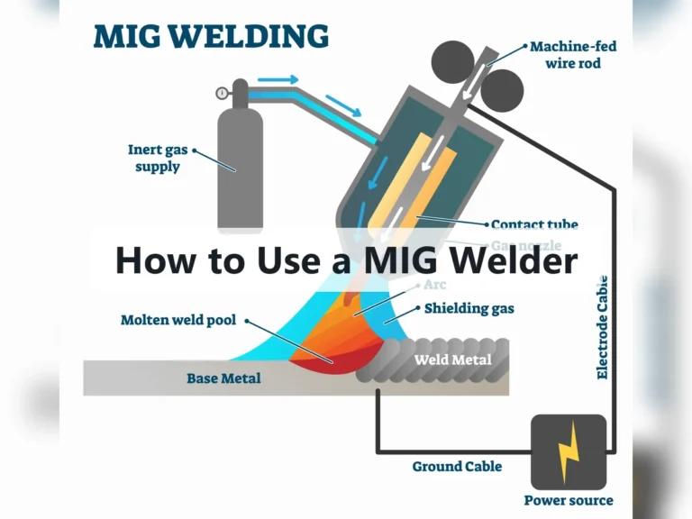
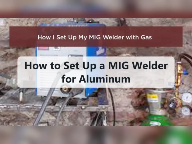
For normal aluminum MIG work, use 100% argon. Do not use the argon-carbon dioxide blend commonly selected for mild steel; carbon dioxide can cause unstable welding, excessive spatter, and poor results on aluminum. Helium or argon-helium mixtures can add heat and penetration, but that extra energy is usually counterproductive on very thin material.
Set gas flow according to the machine, torch, and work environment. Excessive flow can create turbulence that draws air into the shielding envelope, while insufficient flow leaves the puddle vulnerable to oxygen and nitrogen contamination. A moderate, stable flow and protection from fans or drafts are more useful than simply increasing the regulator setting.
Prepare Thin Aluminum Before Striking an Arc
Preparation is especially important when welding aluminum because its surface oxide and contamination can remain in the puddle Aluminum oxide is harder to melt than the parent metal.
Begin by removing paint anodizing sealant and heavy oxidation from both sides of the joint Use a dedicated stainless-steel brush reserved for aluminum brushing the same material with.
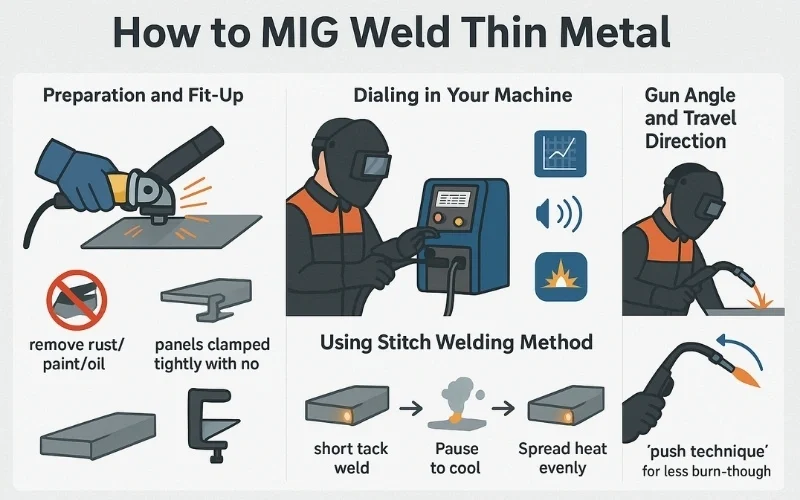
- Remove coatings: Strip paint, anodizing, adhesive, and sealants well beyond the visible weld line.
- Brush correctly: Use a clean stainless-steel brush with firm strokes in one direction rather than a dirty general-purpose brush.
- Degrease: Wipe with a suitable solvent and clean, lint-free cloths; never weld over oil or solvent residue.
- Protect the joint: Keep prepared edges away from bare hands, shop dust, and damp surfaces before welding.
Fit-up matters more than extra power
Thin aluminum should fit closely and consistently. A large gap forces the arc to bridge open space, which increases the chance of burn-through. A tight, even joint lets the wire melt into both edges with less total heat and makes it easier to maintain a controlled puddle.
Use clamps, copper backing, or a properly positioned heat sink when practical. Copper backing can support the molten metal and absorb heat without fusing to aluminum under many conditions. It is not a substitute for correct settings, but it can make a difficult edge joint more manageable.
Clean the joint immediately before welding
Aluminum can begin collecting oxide and airborne contamination soon after cleaning. Prepare only the area you can weld promptly, especially in a humid or dusty shop. If the material becomes visibly dirty again, repeat the cleaning process instead of trying to burn contamination away with a hotter arc.
Never use chlorinated solvents around an active arc. Welding ultraviolet radiation and heat can create hazardous gases from some chlorinated products. Read the solvent label, provide suitable ventilation, and allow any cleaner to evaporate completely before welding.
Set the Welder for Thin Aluminum
There is no single voltage and wire-speed setting that fits every aluminum sheet Thickness alloy joint type wire diameter torch angle and machine design all change the result Start with the manufacturer s aluminum chart or a proven setting for the same wire and thickness.
Most aluminum MIG welding uses a spray-transfer or pulsed approach rather than the short-circuit transfer commonly used for thin steel Spray transfer can create a smooth arc and.
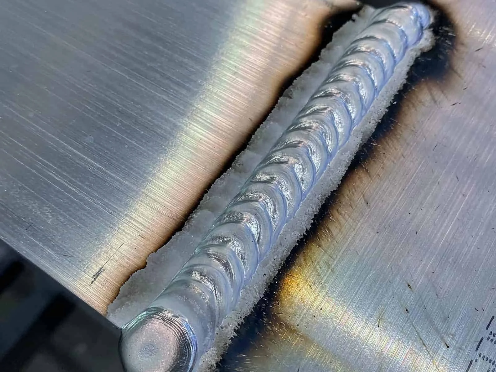
- Start from the chart: Use the wire diameter, material thickness, and shielding-gas combination listed for your machine.
- Watch the puddle: Increase travel speed or reduce output if the edges begin to sag, melt away, or develop a wide crater.
- Check fusion: If the bead sits on top with sharp unmelted toes, add appropriate heat or slow slightly rather than simply making the bead wider.
- Test first: A short practice bead on matching scrap reveals more than a setting copied from unrelated steel work.
Wire speed and voltage work together
In a conventional constant-voltage MIG system, wire speed largely controls amperage while voltage influences arc length and bead shape. Increasing wire speed without enough voltage can make the wire stub into the puddle. Excessive voltage can lengthen the arc, flatten the bead, and increase heat or instability.
This distinction matters when answering “how to mig weld thin aluminum”.
Make one change at a time. If the arc sounds harsh and the wire repeatedly contacts the work, slightly adjust the relationship between wire speed and voltage. If the arc becomes excessively long and the puddle spreads too far, reduce voltage or increase travel speed within the machine’s usable range.
Use the test bead to judge the setting
A useful test bead has a steady arc smooth tie-in at both edges and a controlled profile without scattered pinholes The underside should show appropriate penetration for the.
Begin at one end of the scrap and observe how quickly the material heats. If the first inch looks sound but the final inch melts away, the setting may be marginal for heat buildup. Adjust the welding sequence, allow cooling, or use pulse and shorter stitches rather than blindly lowering the initial setting.
Control Heat, Travel, and Torch Position
The central technique for thin aluminum is to create enough heat for fusion without allowing the sheet to remain hot long enough to burn through Aluminum spreads heat.
Hold a consistent push angle rather than dragging the torch. Pushing generally helps keep the shielding gas ahead of the puddle and lets you see the joint. Keep the arc length short and stable, maintain a predictable contact-tip-to-work distance, and avoid large weaving motions that widen the heated zone.
- Move decisively: A controlled, moderately fast travel speed often works better than pausing to build a large puddle.
- Favor short beads: Stitch sections rather than attempting one uninterrupted pass across a flexible panel.
- Start on thicker metal: When the joint allows, begin on a heavier section and move toward the thin edge so the edge receives less concentrated heat.
- Keep the torch visible: Position your head and hands so you can see the leading edge of the puddle, not only the bright arc.
Use stitch welding to prevent distortion
For long seams, place short welds at spaced intervals, alternating sides or locations to distribute heat. Let each section cool enough to regain stiffness before closing the gaps. A sequence that moves from one end to the other can pull the sheet into a curve, while a balanced sequence reduces cumulative distortion.
Do not cool a hot aluminum weld abruptly with water or compressed air unless the procedure specifically permits it. Rapid cooling can create unwanted stresses and may spread contaminants into the joint. Natural cooling, copper backing, and controlled pauses are safer general approaches.
Understand the puddle’s visual behavior
Aluminum does not always provide the same color cues as steel Instead of waiting for a dramatic red-hot appearance watch the surface tension the way the edges wash.
When the leading edge begins to fold inward or the sheet edge appears to disappear stop advancing the weld and release the trigger Continuing to feed wire into.
Welding Joint Types and Very Thin Sheet
Joint design strongly affects the difficulty of thin aluminum MIG welding A lap joint usually provides more supporting material than a square butt joint while an outside corner.
For a butt joint keep the gap minimal and use backing when possible A slight joint gap may be necessary for penetration on thicker material but an open.
- Butt joint: Use close, even edges and frequent small tacks; support the backside when practical.
- Lap joint: Ensure full contact without trapped oil, moisture, or excessive overlap that creates an inaccessible pocket.
- Corner joint: Direct the arc so both edges melt without lingering at the intersection.
- Repair patch: Match alloy and thickness as closely as possible, and remove fatigue-cracked metal before fitting the patch.
Thin automotive and recreational panels
Body panels, trailer skins, boat components, and small enclosure parts often flex under the arc. Use close clamps and a heat sink where access permits. A long continuous bead can introduce more distortion than the part can tolerate, even when the weld itself has adequate penetration.
Before repairing a cracked panel, determine why it cracked. Vibration, a sharp corner, poor support, corrosion, or an overloaded mounting point can cause a new weld to fail again. A neat bead does not correct a design or fatigue problem underneath it.
When the material is too thin
MIG welding becomes increasingly difficult as aluminum approaches foil-like thickness The wire and arc can deliver more concentrated heat than the sheet can absorb and cleaning or clamping. Keep these limitations in mind when considering “how to mig weld thin aluminum”.
The practical limit depends on the machine and operator, so test on scrap of identical thickness. If repeated trials produce holes even with good fit-up and short pulses, the process is likely a poor match rather than a problem that more practice alone will solve.
Common Problems When MIG Welding Thin Aluminum
Many failed aluminum welds are diagnostic. The bead, arc sound, wire behavior, and backside reveal whether the main issue is contamination, feeding resistance, insufficient fusion, or excessive heat. Change only the likely cause first so you can tell whether the correction worked.
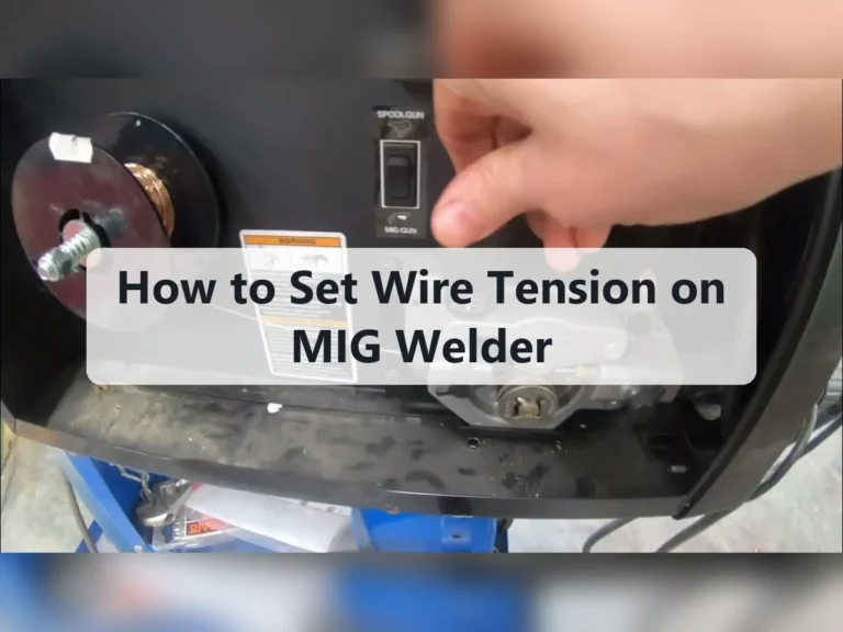
Using the right process does not guarantee a sound weld if the torch cable is sharply bent, the drive-roll pressure is excessive, or the contact tip is loose. Aluminum wire is soft enough that mechanical setup deserves the same attention as voltage and wire speed.
- Bird-nesting: Reduce feeding resistance, inspect the liner, use the correct U-groove rolls, and set only enough drive pressure to feed reliably.
- Porosity: Check gas coverage, drafts, leaks, contamination, and moisture; do not assume more gas flow will solve turbulence.
- Burn-through: Shorten the bead, move faster, reduce heat if appropriate, improve fit-up, and use backing or pulsing.
- Cold lap: Improve cleaning and torch position, then adjust heat or travel so both joint edges actually melt.
Porosity and black residue
Pinholes in the bead usually indicate gas contamination or trapped contaminants. Look for a dirty base metal, oily wire, a leaking gas connection, an empty or incorrectly connected cylinder, excessive wind, or a nozzle obstructed by spatter. Black soot around aluminum welds can also signal inadequate cleaning, poor shielding, or an unstable arc.
Do not simply weld over porous metal. Remove the defective section, clean the surrounding surface, and correct the cause before making a repair pass. Covering porosity can leave hidden voids and make inspection more difficult.
Wire bird-nesting and inconsistent feeding
Bird-nesting occurs when soft wire bunches between the drive rolls and the liner or gun entrance. Common causes include too much drive-roll pressure, a blocked or kinked liner, a worn contact tip, excessive spool drag, or a torch cable bent into a tight loop.
Cut the wire back, remove the tangled section, and inspect the entire feed path. Set roll pressure just high enough to feed without slipping, and verify that the spool unwinds smoothly. Never pull hard on a jammed wire while the drive motor continues running; that can worsen the tangle and damage the feeder.
Burn-through and weak penetration
Burn-through means the heat input has exceeded the sheet s ability to support a puddle It can result from slow travel a long pause at the edge excessive.
Weak penetration is the opposite-looking problem but can have similar causes: poor cleaning, too much travel speed, an arc aimed away from the joint, or insufficient output. Inspect the bead toes and, when possible, bend or section a test coupon. Surface appearance alone cannot prove fusion.
Safety and Inspection Before You Trust the Weld
Wear a welding helmet with the appropriate shade, flame-resistant clothing, gloves, closed footwear, and eye protection during grinding and brushing. Aluminum reflects arc light strongly, and the bright puddle can encourage poor viewing habits. Use local ventilation or suitable respiratory protection where coatings, paint, or unknown residues may create fumes.
Keep the work area free of flammable materials, secure the gas cylinder, and inspect hoses and electrical leads before use. Welding produces ultraviolet radiation, hot metal, sparks, and compressed-gas hazards even when the workpiece is small. Do not weld containers, tanks, or enclosed sections that may contain residue without an appropriate safety procedure.
- Ventilation: Remove fumes at the source and identify coatings before heating them.
- Fire control: Check behind and beneath the workpiece for hidden combustibles, especially on vehicles and trailers.
- Gas protection: Secure the cylinder upright and inspect the regulator, hose, and connections for leaks or damage.
- Hot-metal control: Mark or isolate recently welded parts so another person does not handle them unexpectedly.
Inspect the finished bead
Clean the weld so its shape and surface are visible. Look for continuous tie-in, an even profile, no visible cracks, no crater at the stop, and no clusters of pinholes. Check the opposite side for excessive sag, incomplete penetration, or a sharp burn-through edge.
For noncritical repairs, a visual inspection plus a test weld on matching scrap may be adequate. Structural, pressure-containing, lifting, safety-critical, or code-governed work requires the applicable procedure, qualified personnel, and inspection method rather than an informal assessment.
FAQ: How to MIG Weld Thin Aluminum
Can a regular MIG welder weld thin aluminum?
Yes, if it accepts aluminum wire, provides the correct polarity and settings, and can feed the soft wire reliably. A spool gun or push-pull gun is usually easier than routing aluminum wire through a long standard torch.
Very thin sheet may still be impractical on a basic machine because its minimum output and transfer characteristics can exceed the material’s heat tolerance.
What gas should I use for thin aluminum MIG welding?
Use 100% argon for typical aluminum MIG work. Avoid the argon-carbon dioxide mixtures used for many steel applications, because they are not an appropriate general shielding gas for aluminum.
Should I push or pull the MIG gun on aluminum?
Use a modest push angle so the shielding gas leads the puddle and the joint remains visible. Keep the angle and arc length consistent; an extreme angle can disturb shielding or direct heat away from the joint.
Why does aluminum MIG wire keep bird-nesting?
The wire may be encountering too much resistance from a kinked liner, excessive drive-roll pressure, a worn tip, tight torch bends, or incorrect spool tension. Install the appropriate liner and U-groove rolls, then reduce pressure to the minimum that feeds consistently.
How do I stop thin aluminum from burning through?
Improve fit-up, use a heat sink or backing, shorten the weld, travel steadily, and allow cooling between stitches. Start from a tested machine setting and adjust heat only after checking contamination, gaps, torch position, and feeding problems.
Do I need to remove aluminum oxide before welding?
Yes. Remove heavy oxide and coatings with a dedicated stainless-steel brush, then degrease with a suitable cleaner. Oxide and contamination can interfere with fusion and contribute to porosity, especially on thin material.
Is MIG or TIG better for very thin aluminum?
TIG generally offers finer control for extremely thin sheet, delicate edges, and visible precision work. MIG is faster and practical for suitable thicknesses, repairs, and longer seams, but its wire and arc typically deliver heat less gently.
Conclusion
Reliable results come from treating thin aluminum as a heat-control and cleanliness problem not simply a low-amperage welding task Use the correct wire-feeding system pure argon clean close-fitting.
With those limits understood, how to mig weld thin aluminum becomes a repeatable shop skill: prepare carefully, test on matching scrap, make the shortest sound weld possible, and inspect both sides before trusting the repair.
Set up a spool gun with aluminum wire and pure argon, then practice short beads on matching scrap until the puddle ties in without sagging or pinholes.