How to Build a MIG Welder: Setup Steps and Troubleshooting Tips
You can build a practical MIG welding setup by assembling a compatible power source, wire feeder, shielding-gas system, gun, work lead, and correctly rated electrical supply.
However building a MIG welder from individual electrical components is not the same as setting up a commercial machine A MIG welder contains hazardous mains voltage high welding.
That distinction matters because a familiar assumption can lead beginners in the wrong direction if a welder is essentially a transformer motor spool and torch it may seem. This guide examines “how to build a mig welder” and explains the details that matter in practice.
- ✓A safe MIG setup requires matched power, wire-feed, gun, work-lead, gas, and electrical components.
- ✓Do not improvise mains isolation, protection circuits, or high-current output wiring.
- ✓Correct polarity, wire type, shielding gas, voltage, wire speed, and stick-out must work together.
- ✓Most welding faults can be narrowed down by checking wire delivery, gas coverage, electrical connections, and settings in that order.
What “Building” a MIG Welder Actually Involves
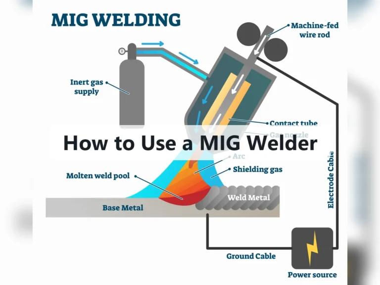
A MIG or metal inert gas welder creates an arc between a continuously fed electrode wire and the workpiece The wire melts into the joint while a shielding.
There are two very different projects hidden behind the phrase how to build a mig welder The first is a system setup selecting a commercial power source and.
A home-built power source must deliver stable direct current across changing arc conditions It must also prevent dangerous voltage from reaching the operator survive short circuits dissipate heat.
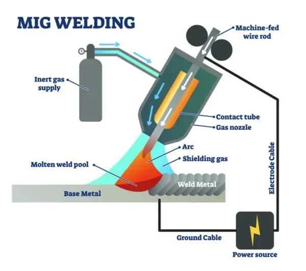
- Practical interpretation: Treat “build” as assembling and configuring a complete MIG system unless you have specialized power-electronics experience.
- Core function: The power source supplies welding current while the feeder controls how quickly the electrode reaches the arc.
- Safety boundary: Never bypass a factory interlock, protective earth, fuse, thermal sensor, or enclosure.
- Material scope: Wire, gas, polarity, voltage, and feed speed must be selected as one coordinated process.
Why a commercial machine is usually the better foundation
A listed or properly certified welder normally includes isolation, cooling, overcurrent protection, output terminals, a contactor, and controls designed to work together. It may also include a spool-gun connection, gas solenoid, burn-back control, inductance adjustment, or a chart for common wire and material combinations.
That does not mean every commercial machine is suitable for every job A compact 120-volt unit may be convenient for sheet metal but limited by input current and.
What a true DIY power source would need
A scratch-built unit would need a protected input stage isolation from the supply a controlled welding output rectification or high-frequency switching as appropriate current limiting a stable wire-feed.
Design errors can cause electric shock arc flash fire uncontrolled wire feeding or destruction of the workpiece and machine Because these risks are difficult to evaluate from a.
Parts Required for a Safe MIG Welding Setup
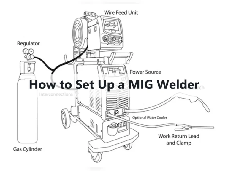
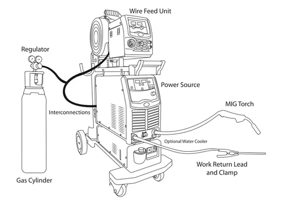
Before connecting anything identify the complete path from the electrical outlet to the weld and back again The input cord feeds the power source The power source supplies.
Every component has to be compatible A gun connector that physically fits may still have the wrong trigger wiring liner gas passage or current rating Likewise a regulator.
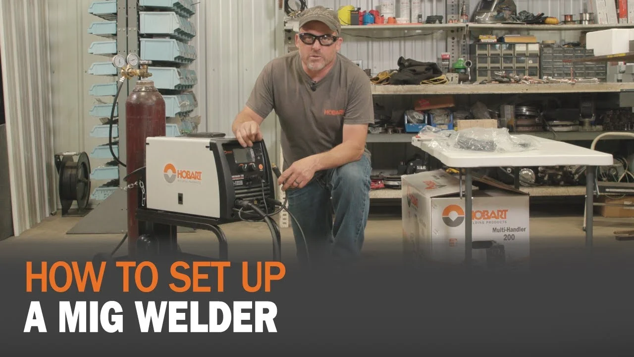
- Power source: Confirm input voltage, output range, duty cycle, polarity options, and wire sizes supported.
- Wire path: Match the drive rolls, liner, guide tube, contact tip, and gun to the electrode diameter and type.
- Gas equipment: Use the correct cylinder, regulator or flowmeter, hose, fittings, and cylinder restraint.
- Return circuit: Inspect the work lead, clamp, output connector, and clean metal contact at the workpiece.
Power source and electrical supply
The power source may be a transformer-rectifier machine or an inverter. Transformer machines are often heavier and mechanically straightforward, while inverter machines are lighter and may offer more refined control. Either type can produce good welds when properly matched to the job.
Read the data plate for input voltage input amperage recommended circuit protection and duty-cycle information Do not assume a household receptacle can support a machine because the plug.
Gun, liner, contact tip, and drive rolls
The gun carries the electrode wire, shielding gas, and trigger circuit. Inside it, the liner guides the wire from the feeder to the contact tip. The tip transfers welding current to the wire while allowing the wire to extend beyond it as stick-out.
Drive rolls must grip the wire without flattening it V-groove rolls commonly suit solid wire while knurled or U-groove styles may be used for certain flux-cored or softer.
Shielding gas and regulator
Solid MIG wire normally requires external shielding gas A common mild-steel mixture is argon with carbon dioxide while straight carbon dioxide can provide deeper penetration and more spatter.
Keep the cylinder upright and secured with a chain or strap Inspect the valve regulator hose and fittings before opening the cylinder Do not use oil or grease.
Wire selection and polarity
Solid ER70S-type steel wire is commonly used with a shielding-gas setup and usually runs with electrode-positive polarity but always follow the wire and machine instructions Self-shielded flux-cored wire may use a different polarity and.
Aluminum wire presents additional feeding challenges because it is soft A short gun suitable liner correct drive rolls and sometimes a spool gun help prevent bird-nesting Stainless wire.
How to Build a MIG Welder Setup Step by Step
Once the parts are matched assemble the system with the power disconnected and the gas cylinder closed Keep the gun cable and work lead arranged so they will.
Do not begin by turning knobs until the wire path, return circuit, and gas supply have been checked. Many apparent “settings” problems are actually loose terminals, a blocked liner, an empty cylinder, or a work clamp attached to painted metal.
- Start de-energized: Unplug the machine or switch off its disconnect before installing wire or opening access panels.
- Build the return path: Attach the work lead to a clean, solid section of the workpiece or welding table.
- Protect the feed path: Keep the gun cable reasonably straight and use the correct liner, tip, and drive-roll groove.
- Verify before striking: Confirm polarity, gas flow, wire direction, and control settings with the machine manual.
- Place and secure the machine. Set it on a stable, dry surface with clearance around ventilation openings. Keep flammable materials away from the machine and welding area.
- Connect the work lead. Insert the lead into the correct output terminal if the machine uses removable connections. Tighten it securely, then attach the clamp to clean conductive metal.
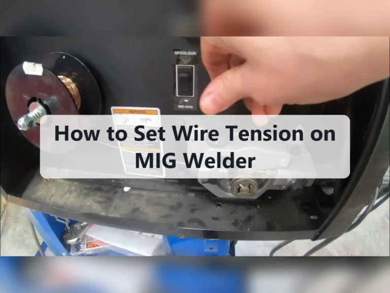
- Install the spool. Fit the spool so wire unwinds in the direction shown by the machine. Set the hub tension just high enough to stop the spool from overrunning.
- Install the drive rolls and guide parts. Match the groove and markings to the wire diameter. Thread the wire through the inlet guide, rolls, outlet guide, liner, and contact tip as directed.
- Set feed-roll pressure. Begin with light pressure and increase it only enough to feed smoothly. Test by pinching the wire carefully downstream of the rolls; never place fingers near moving rollers or the energized tip.
- Connect the gun. Seat the gun connector fully and tighten its retaining collar if present. Verify that the trigger activates the feeder and gas solenoid without sticking.
- Connect the gas system. Secure the cylinder, inspect the regulator connection, attach the hose, and open the cylinder valve slowly. Check for leaks with an approved leak-detection solution, never with a flame.
- Set polarity. Compare the machine’s terminal arrangement with the wire manufacturer’s polarity requirement. Flux-cored and solid-wire processes are not automatically interchangeable.
- Thread and trim the wire. Remove the contact tip if the manual recommends doing so during loading, then feed wire through the gun. Reinstall the correct tip and nozzle after the wire emerges.
- Perform a dry check. With appropriate protective equipment, confirm that the trigger feeds wire and starts gas flow. Keep the gun pointed away from people, cylinders, and flammable materials.
Preparing the joint
Remove paint rust mill scale oil and moisture from the joint and the area where the work clamp attaches Contamination consumes shielding quality and can create porosity inclusions.
Fit-up also matters. Excessive gaps require more heat and filler, while a tight or poorly aligned joint can prevent penetration. Clamp the pieces so they remain aligned, but leave enough access for the gun angle and travel path.
Tack weld first when distortion or movement is likely.
Choosing initial settings
Use the machine s chart as the starting point for material thickness wire type wire diameter and gas Voltage primarily influences arc length and bead width while wire-feed.
Begin on scrap made from the same material and with similar thickness Set a comfortable gun angle maintain a consistent stick-out and listen to the arc A smooth.
Safety Checks Before You Strike an Arc
Welding combines intense ultraviolet radiation, hot metal, fumes, sparks, compressed gas, and electricity. A complete setup is not ready merely because the wire feeds. Establish ventilation, shielding, clothing, and fire controls before testing the arc.
Wear a properly rated welding helmet with the correct shade for the process safety glasses under the helmet flame-resistant clothing gloves and closed leather footwear Protect nearby workers.
- Electrical protection: Keep the machine dry, preserve the grounding path, and do not weld with damaged cords or exposed conductors.
- Fume control: Use local exhaust or effective ventilation and never weld coatings whose contents are unknown.
- Cylinder control: Secure cylinders upright, protect valves, and keep them away from heat, sparks, and impact.
- Fire watch: Inspect both sides and the opposite side of a joint for hidden combustibles before and after welding.
Do not weld on closed tanks, drums, pipes, or containers that may have held flammable or toxic substances unless they have been professionally cleaned and made safe. Do not weld near flammable vapors even if the container appears empty. Heated residues can ignite or expand violently.
Ventilation is especially important when welding galvanized steel, painted surfaces, stainless alloys, or unknown coatings. Remove coatings where appropriate, use suitable respiratory controls when required, and stop if fumes cause symptoms such as dizziness, nausea, headache, or breathing irritation.
Heat, duty cycle, and machine limits
Duty cycle describes how long a machine can weld within a stated time period at a stated output before it needs to cool Running continuously at high output.
Let the cooling fan operate and keep vents clear. Do not defeat a thermal shutdown to continue working. If the machine becomes unusually hot, smells of burning insulation, trips its breaker, or produces inconsistent output after warming up, stop and investigate.
Tuning the Arc: Settings That Work Together
Good welds come from a coordinated group of variables rather than one perfect dial position Wire diameter material thickness joint design gas polarity voltage wire speed travel speed.
For a short-circuit steel setup too little voltage can produce a stubby erratic arc and excessive spatter Too much voltage can make the arc long and unstable flatten.
- Stick-out: Keep the electrode extension consistent and within the range recommended for the wire and process.
- Gun angle: Use a modest travel angle and aim the arc deliberately at the joint rather than wandering across both edges.
- Travel speed: Move fast enough to avoid a cold, oversized bead but slowly enough to establish fusion.
- Gas coverage: Shield the arc from wind and turbulence; outdoor welding may require screens or a different process.
Reading the bead
A useful practice bead should tie into both sides of the joint have a consistent width and show a controlled transition at the toes A tall narrow bead.
Visual appearance cannot reveal every internal defect. Critical structural work may require qualified procedures, inspection, and a trained welder. Do not use a visually attractive practice bead as proof that a safety-critical repair is sound.
Gas flow and nozzle position
Keep the nozzle clean and ensure the gas diffuser is not blocked by spatter. Hold the nozzle close enough to protect the arc without dragging it through the puddle. A damaged nozzle can disturb flow and reduce coverage.
Wind can carry shielding gas away before it reaches the puddle. If a breeze is present, use a suitable screen and avoid creating turbulence with excessive flow. More gas is not always better; high flow can pull surrounding air into the shield.
How to Troubleshoot a MIG Welder Setup
When a MIG welder performs badly, troubleshoot from the simplest external cause toward the internal machine. Start with the material, wire, gas, connections, and consumables before opening the enclosure. Internal repairs involve hazardous energy and should be performed only by a qualified technician.
The exact phrase how to build a mig welder often brings people to troubleshooting because a newly assembled setup may feed wire without producing a usable weld. Separate the problem into four systems: wire delivery, shielding gas, electrical return, and arc settings. This prevents random knob adjustments.
- No arc: Check input power, trigger operation, polarity, work-clamp contact, output connections, and the machine’s contactor.
- Wire stubbing: Check drive-roll tension, liner restriction, contact-tip size, wire speed, and voltage balance.
- Porosity: Check gas supply, leaks, nozzle blockage, wind, surface contamination, and excessive stick-out.
- Burn-back: Check low wire speed, excessive voltage, contact-tip distance, and burn-back settings.
| Symptom | Likely causes | First checks |
|---|---|---|
| Wire will not feed | Empty spool, jammed liner, seized drive roll, trigger fault | Spool path, pressure, liner, gun connection |
| Wire feeds but arc is weak | Poor return, wrong polarity, low input supply, loose terminal | Clamp location, output connections, polarity, power supply |
| Heavy spatter | Wrong settings, contamination, poor stick-out, unstable gas | Clean joint, chart settings, nozzle, gas flow |
| Weld has holes | Insufficient shielding or dirty material | Gas level, leaks, wind, nozzle, surface preparation |
| Machine overheats | Excessive duty cycle, blocked ventilation, undersized supply | Cooling clearance, duty cycle, input circuit |
No wire feeding or irregular feeding
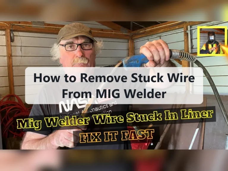
First check whether the spool is rotating freely and whether the wire has crossed underneath itself. Then inspect the inlet guide, drive-roll groove, outlet guide, liner, and contact tip. A sharp bend in the gun cable can add enough resistance to make feeding erratic.
If the motor runs but the wire slips, increase roller pressure gradually. If the wire becomes flattened, reduce pressure and inspect whether the roll is the correct type. A bird’s nest at the feeder usually means the wire encountered resistance downstream while the rolls continued pushing it.
Porosity, soot, or a dirty-looking weld
Porosity often points to lost shielding. Check that the cylinder contains gas, the regulator is flowing, the hose and fittings are intact, and the solenoid opens when the trigger is pressed. Inspect the nozzle for spatter and verify that the diffuser and gas passage are clear.
Also check the work surface. Oil, moisture, rust, paint, and galvanizing can create gas and contamination in the puddle. If porosity appears only outdoors, wind is a strong suspect.
Clean the joint and run a controlled test with a wind screen before changing several electrical settings.
Arc starts poorly or the wire burns back
A poor start may result from an oxidized contact tip, incorrect stick-out, a loose work connection, or a setting mismatch. Replace worn consumables and ensure the tip fits the wire closely without binding. Check that the trigger, gas solenoid, and contactor operate in the correct sequence.
Burn-back occurs when the wire melts up to the contact tip at the end of a weld Common causes include low wire-feed speed relative to voltage excessive stick-out.
Machine trips a breaker or shuts down
A breaker trip can result from an overloaded circuit, incorrect input voltage, an extension cord that is too long or too small, a shorted component, or a machine fault. Disconnect the welder and do not repeatedly reset the breaker while the cause is unknown.
Thermal shutdown after extended welding may be normal if the duty cycle has been exceeded. Shutdown at low output or during brief use is not normal enough to ignore. Keep the machine out of service until its ventilation, supply, and internal condition have been evaluated.
Maintenance and Storage That Prevent Repeat Problems
Maintenance is mostly inspection and contamination control. Before each session, examine the power cord, plug, gun cable, trigger, work lead, clamp, gas hose, regulator, cylinder restraint, and output terminals. Replace damaged parts rather than wrapping them temporarily with tape.
Clean spatter from the nozzle and replace worn contact tips. Keep the wire dry and covered because rust or surface contamination increases feeding resistance. When changing wire types or diameters, update the drive rolls, liner, contact tip, polarity, and settings as necessary.
- After each use: Close the cylinder valve, bleed or relieve the regulator according to its instructions, and store the gun where it will not be crushed.
- Before storage: Protect wire from humidity and keep the machine dry, clean, and ventilated.
- During inspection: Look for hot spots, discoloration, cracked insulation, loose connectors, and unusual fan noise.
- For internal service: Unplug the machine and use a qualified technician because capacitors may retain dangerous energy.
When to stop using the machine
Stop immediately if you feel an electrical shock, see smoke, smell burning insulation, hear repeated arcing inside the enclosure, find a damaged grounding conductor, or observe uncontrolled wire movement. Do not open a powered machine to locate the problem.
A homemade or modified machine deserves an especially conservative inspection standard. If the enclosure, grounding, insulation, output isolation, or protective controls are uncertain, the safest repair is to replace the power source with a properly engineered unit rather than continue refining the design.
FAQ: Building and Setting Up a MIG Welder
Can a beginner build a MIG welder from scratch?
A beginner can assemble a MIG welding setup from a suitable commercial machine and compatible accessories. Building the mains-powered power source itself is not a beginner project because it involves shock, fire, stored-energy, and high-current hazards.
Can I convert a stick welder into a MIG welder?
Sometimes a compatible constant-voltage power source can operate a wire feeder, but a typical stick welder is not automatically suitable. MIG requires appropriate voltage behavior, wire-feed control, gun connections, shielding