MIG Welder Settings Chart: Practical Guide and Important Details
A MIG welder settings chart is a starting point, not a guarantee; match wire diameter and material thickness, then fine-tune voltage and wire speed on scrap metal.
A setting that works perfectly on clean 1 8-inch steel can produce a cold weld excessive spatter or burn-through on a rusty tightly fitted or overheated joint The.
This guide explains how to read a mig welder settings chart without treating it as an automatic recipe You will learn what voltage and wire-feed-speed controls actually change.
- ✓Use material thickness and wire diameter to select a starting range, then validate it with a test weld.
- ✓Voltage mainly affects arc length and bead profile; wire feed speed strongly affects amperage and penetration.
- ✓Gas type, polarity, stick-out, travel speed, and joint fit can make the same dial settings behave differently.
- ✓Read the bead and listen to the arc instead of relying on numbers alone.
How to Read a MIG Welder Settings Chart
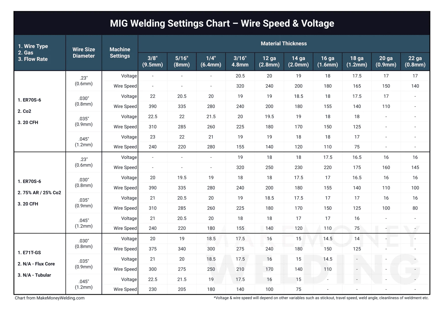
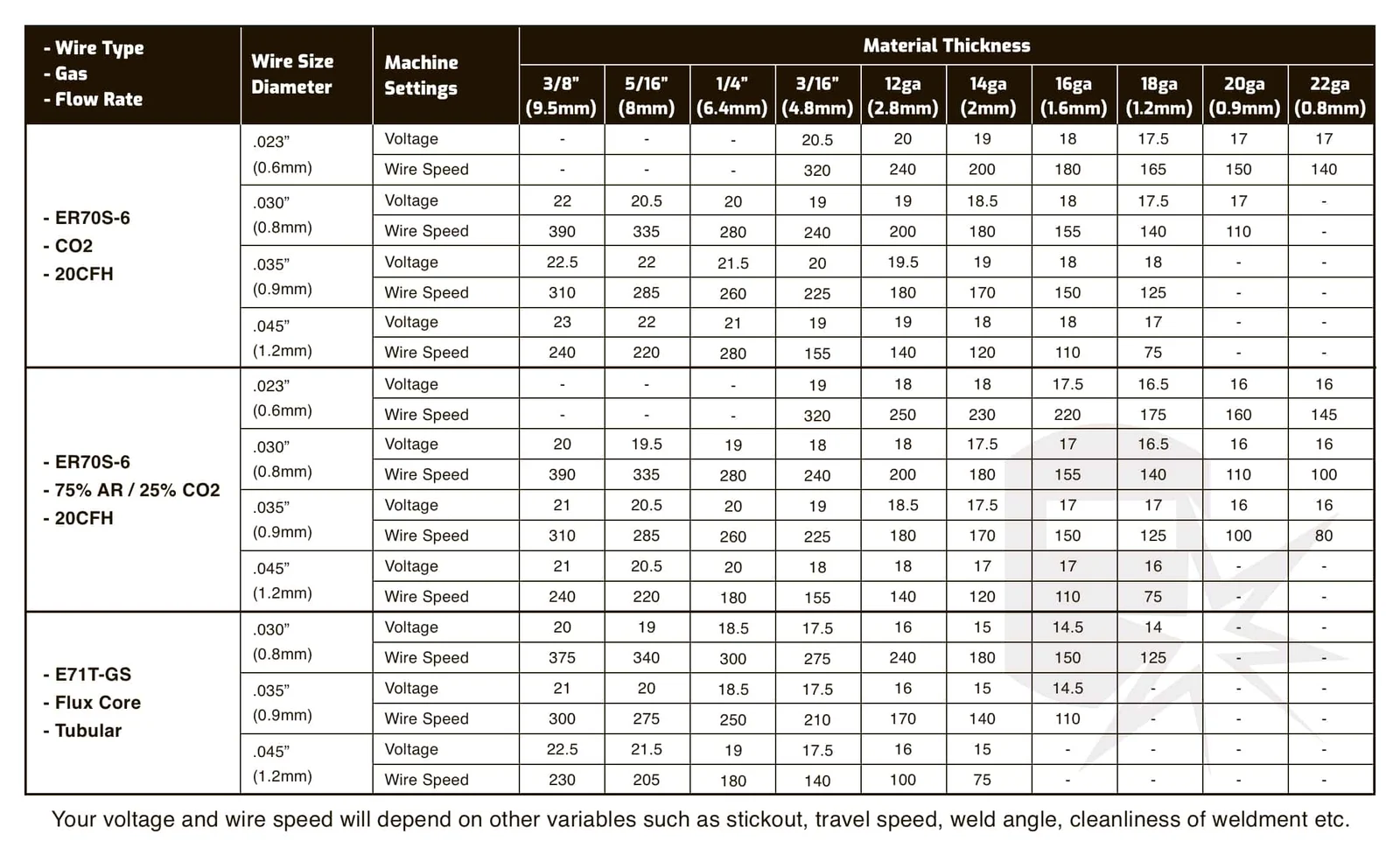
A chart normally connects four variables: wire diameter, base-metal thickness, wire-feed speed, and voltage. Some charts also list shielding gas, polarity, transfer mode, recommended amperage, or a range of travel speeds. These values are intended to place the arc in a workable operating window, not to eliminate adjustment.
For a conventional constant-voltage MIG machine, wire-feed speed is closely related to welding current. Increasing feed speed generally increases amperage and deposition, while voltage changes the arc length and influences bead width and smoothness. Because the controls interact, changing one setting often requires a small correction to the other.
- Material: Identify the actual base metal and account for coatings, rust, heat sinks, and joint thickness.
- Wire: Confirm diameter, alloy, spool condition, and whether the wire is solid or flux-cored.
- Gas: Match the chart’s shielding-gas recommendation; gas changes arc behavior and allowable settings.
- Machine: Check whether the chart applies to your voltage range, gun polarity, and duty cycle.
Starting chart for solid wire on mild steel
The following table is a practical starting reference for common solid ER70S-series wire with a typical argon/carbon-dioxide mix. It is deliberately presented as a range because machines, gas blends, joint positions, and manufacturers differ. Use the narrowest useful range first, then make small changes while welding.
| Wire diameter | Approximate steel thickness | Starting voltage | Starting wire-feed speed | Typical use |
|---|---|---|---|---|
| 0.023 in | 22 gauge to 1/8 in | 15–18 V | 150–350 ipm | Sheet metal and light repair |
| 0.030 in | 20 gauge to 3/16 in | 16–20 V | 150–400 ipm | General fabrication and automotive work |
| 0.035 in | 18 gauge to 1/4 in | 18–22 V | 180–450 ipm | Heavier fabrication |
| 0.045 in | 3/16 in and thicker | 21–26 V | 200–500 ipm | High-deposition work on larger machines |
These ranges are not suitable for every machine. A compact 120-volt welder may not have the output needed for the upper end, while a larger industrial machine may operate poorly at the lowest settings. If your welder has a manufacturer chart printed on the door or supplied in its manual, use that information first.
Choosing Wire, Gas, Polarity, and Material Thickness
The best settings begin before you turn the voltage knob Wire diameter determines how easily the machine can control a low-current arc how much metal it deposits and.
For ordinary clean mild steel, solid ER70S-6 wire is a common choice because its deoxidizers tolerate a modest amount of surface contamination better than some other solid wires. It still requires cleaning. A dirty joint can trap gas, produce porosity, and make a perfectly reasonable chart setting appear defective.
- Solid wire: Usually runs with shielding gas and direct-current electrode positive, often called DCEP or reverse polarity.
- Self-shielded flux core: Often uses a different polarity and does not require an external gas bottle; follow the wire label.
- Stainless steel: Requires compatible stainless wire, suitable shielding gas, and careful heat control to limit distortion.
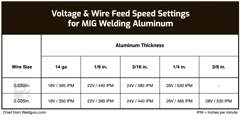
- Aluminum: Commonly needs a spool gun or push-pull setup, a soft liner, a suitable aluminum wire, and 100 percent argon.
Gas selection changes the chart
A common general-purpose blend for solid-wire mild steel is argon with carbon dioxide. More carbon dioxide typically increases penetration and arc aggressiveness, while a higher argon content can produce a smoother arc and less spatter in appropriate applications. The exact result depends on the blend and machine.
Pure carbon dioxide can be economical and offers useful penetration, but it usually creates more spatter and a harsher arc than an argon-rich mixture. Do not substitute gas casually when following a chart: the same voltage and wire speed can behave differently with a different gas.
Thickness is not the whole joint
Two pieces of the same thickness may require different approaches A lap joint can draw heat away differently from a butt joint and a large plate may act.
For material near the machine’s limit, beveling a thick edge and using several controlled passes can be more reliable than trying to force one extremely hot pass. For thin material, stitch welding or short intermittent beads can reduce distortion and prevent the surrounding metal from becoming too hot.
Voltage, Wire Feed Speed, and Amperage Explained
Voltage controls the electrical pressure that helps establish arc length If voltage is too low for the selected wire-feed speed the wire may push into the puddle causing.
Wire-feed speed controls how quickly filler metal enters the arc. On most constant-voltage MIG equipment, increasing it increases welding current and deposition rate. This is why a chart may list wire-feed speed rather than amperage as the primary control, especially on machines designed for hobby and light-fabrication use.
- Too little feed: The arc may hiss or break up, and the bead can become narrow with inadequate fill.
- Too much feed: The wire may stub into the work, the gun may push back, and spatter can increase.
- Too little voltage: Expect a short, aggressive arc and a tall, rope-like bead.
- Too much voltage: Expect a long arc, a wide or flat bead, excess spatter, or undercut.
Inductance, trim, and synergic controls
Some machines include inductance arc control voltage trim or synergic programs These features alter how quickly current rises and how the machine responds to short circuits or changes in arc length A higher inductance setting can produce a softer.
Synergic machines may automatically pair wire-feed speed and voltage based on material, wire, and gas selections. That convenience is useful, but it does not replace a test bead. Confirm the wire diameter, gas, and polarity before assuming the displayed program is correct.
Short-circuit, spray, and pulsed transfer
Short-circuit transfer is commonly used at lower settings and works well for thinner steel and out-of-position welding when properly controlled. The wire repeatedly contacts the puddle, and the arc reestablishes between short circuits.
Spray transfer uses higher current and voltage with a suitable argon-rich gas. It can provide smooth, high-deposition welding on thicker material, but it generally creates a larger, hotter puddle and is less suitable for thin sheet or many out-of-position applications.
Pulsed MIG alternates current to control heat and droplet transfer. Its settings cannot be interpreted using a basic short-circuit chart. Select the correct program and follow the machine’s guidance for wire, gas, material, and position.
How to Fine-Tune a Chart Setting on the Workpiece
Begin with clean scrap made from the same material and close to the same thickness as the job. Install the correct contact tip, set the recommended polarity, verify gas flow, and make a bead while holding a consistent travel angle and stick-out. A chart is most useful when the physical welding technique is controlled.
This is an important consideration for mig welder settings chart.
Listen to the arc and inspect the bead after it cools. A consistent, controlled crackle is often a useful sign in short-circuit MIG, but sound alone cannot confirm penetration or strength. If the joint matters structurally, inspect the fusion at an appropriate cut, bend, or other qualified test rather than judging the surface only.
- Start in the middle: Choose the center of the chart’s suggested voltage and feed range rather than the maximum.
- Change one variable: Adjust voltage or feed speed in small increments so you can identify cause and effect.
- Watch the puddle: Keep the leading edge of the puddle directed into both sides of the joint.
- Record the result: Note wire, gas, settings, position, and travel speed for repeatable work.
- Prepare the joint. Remove paint, oil, mill scale, rust, and moisture from the weld area. Clamp the parts so the gap and alignment remain stable.
- Set the machine. Confirm wire diameter, polarity, gas, drive-roll groove, contact tip, and the chart’s starting values.
- Make a test bead. Use the same position and direction planned for the finished weld. Avoid changing travel speed while evaluating machine settings.
- Correct wire-feed problems first. If the wire stubs or surges, check feed tension, liner condition, tip size, and spool drag before making large electrical adjustments.
- Fine-tune the arc. Adjust voltage slightly for arc length and bead shape, or adjust wire speed for deposition and current. Re-test after each change.
Technique variables that imitate bad settings
Long stick-out reduces effective heating at the joint and can make a weld appear cold. Very short stick-out can increase heat at the contact tip and make the arc feel aggressive. For many short-circuit applications, a consistent stick-out around 3/8 inch is a reasonable starting practice, but the wire and process instructions take precedence.
A gun angle that is too steep can push shielding gas away or bury the arc in the leading edge. Excessive travel speed makes a narrow bead with poor sidewall fusion, while moving too slowly can create an overly wide, convex, or overheated bead. Correct technique before chasing the chart.
Reading Bead Appearance and Troubleshooting Results
A sound-looking bead is reasonably uniform in width, has smooth tie-in at both toes, and follows the joint without abrupt craters or heavy spatter. The correct appearance varies with process and position, so a flat, shiny surface is not automatically proof of adequate penetration.
When a weld fails visually, identify whether the problem is electrical, mechanical, metallurgical, or environmental. The mig welder settings chart may be accurate while the actual gas coverage is poor, the wire is contaminated, or the work clamp is making intermittent contact.
- Ignoring contamination: Paint, oil, moisture, and galvanized coatings can cause porosity and hazardous fumes.
- Changing everything: Large simultaneous adjustments make troubleshooting guesswork.
- Over-trusting amperage: Displayed amperage may be estimated or may change with stick-out and travel conditions.
- Skipping fit-up checks: A gap, mismatch, or poor clamp can change heat flow more than a small dial adjustment.
| Observed result | Likely causes | Useful correction |
|---|---|---|
| Wire stubs into the puddle | Feed speed too high for voltage, low voltage, poor feeding, or excessive stick-out | Increase voltage slightly or reduce feed; inspect liner, tip, and drive rolls |
| Long, erratic arc with spatter | Voltage too high, inadequate grounding, wrong polarity, or poor gas | Reduce voltage, check work lead and polarity, and verify gas delivery |
| Tall, narrow bead | Low voltage, slow wire feed, fast travel, or insufficient heat | Balance voltage and feed, slow travel appropriately, and check joint preparation |
| Wide, flat bead or undercut | Voltage too high, travel too fast at the toes, or excessive heat | Reduce voltage or travel speed as appropriate and improve gun angle |
| Pinholes or bubbles | Gas leaks, wind, blocked nozzle, contamination, or damp flux-core wire | Clean the nozzle, check flow and leaks, shield from drafts, and clean the metal |
| Burn-through | Too much heat, excessive gap, slow travel, or thin material | Lower settings, use smaller wire, bridge with short stitches, or improve fit-up |
When spatter is the clue
Some spatter is normal, particularly with short-circuit transfer and carbon-dioxide-rich gas. Excessive spatter often points to an imbalance between voltage and wire speed, but it can also result from contaminated steel, poor grounding, incorrect polarity, an unstable liner, or a damaged contact tip.
Do not solve every spatter problem by lowering voltage. If feed speed remains high while voltage drops, the wire may repeatedly collide with the puddle. Make a small adjustment, listen to the arc, and inspect the wire path before continuing.
Settings for Thin Steel, Thick Steel, Stainless, and Aluminum
Thin steel rewards restraint. Use the smallest practical wire, clean the joint thoroughly, keep the arc moving, and consider short stitch welds rather than one continuous bead. Backing material can absorb heat, but it must fit closely and should not create an unintended hazard or inaccessible trapped space.
Thicker steel may require higher wire-feed speed, greater voltage, preheating where appropriate, beveling, and multiple passes. Preheating is not a universal cure: it can increase distortion and may be unsuitable for certain alloys or coated materials. Follow the applicable welding procedure when the work is safety-critical.
- Thin mild steel: Favor low heat input, small wire, short beads, and a tight fit-up.
- Thick mild steel: Confirm available machine output, joint preparation, interpass cleaning, and pass sequence.
- Stainless: Use stainless-compatible consumables and avoid excessive heat that can discolor or distort the joint.
- Aluminum: Keep the wire path smooth, prevent bird-nesting, and use the correct spool-gun or push-pull setup.
Stainless steel considerations
Stainless wire and shielding gas must be compatible with the base alloy and desired weld properties. Stainless transfers heat differently from mild steel and can distort readily, so a chart should be treated as an initial electrical reference rather than a complete procedure.
Cleanliness is especially important. Use tools dedicated to stainless steel so carbon-steel contamination does not become embedded in the surface. Allow adequate shielding after the arc stops when the process and consumable call for it.
Aluminum considerations
Aluminum wire is soft and can buckle between the drive rolls and contact tip. Correct drive-roll pressure, a clean liner or gun path, a suitable contact tip, and minimal drag are essential. A spool gun shortens the flexible path and is often easier to control on smaller equipment.
Aluminum oxide melts at a much higher temperature than the base aluminum. Remove oxidation with a clean stainless brush reserved for aluminum, then weld promptly. Excessive cleaning pressure can smear contamination instead of removing it.
Safety and Equipment Checks Before Welding
Settings cannot compensate for unsafe preparation. Wear an appropriate welding helmet with the correct shade, flame-resistant clothing, gloves, closed footwear, and hearing or respiratory protection when the task requires it. Keep combustible materials away from sparks and provide ventilation that removes fumes without blowing away shielding gas.
Galvanized, painted, solvent-cleaned, or unknown metals deserve special caution. Coatings can produce hazardous fumes, and enclosed spaces can accumulate toxic gases or displace oxygen. Remove coatings where practical, identify the material, and use suitable ventilation and respiratory controls.
- Gas cylinder: Secure it upright, protect the valve, and inspect hoses and connections for leaks.
- Electrical setup: Keep the work clamp clean and close to the joint; inspect cables and the gun for damage.
- Fire control: Check both sides and nearby areas for sparks, especially behind walls or under floors.
- Machine limits: Respect duty cycle and allow cooling; repeated overloads can damage equipment.
Maintenance that protects setting accuracy
A worn contact tip can create an inconsistent electrical connection and make the arc surge. Replace it when the opening becomes oversized, damaged, or clogged. Keep the nozzle free of spatter so gas can flow evenly around the wire.
Inspect the liner, drive rolls, spool brake, and ground connection when wire feed becomes erratic. Excessive drive-roll pressure can deform wire, while insufficient pressure causes slipping. Set pressure only high enough to feed reliably.
FAQ: MIG Welder Settings Chart Questions
What is the best setting on a mig welder settings chart?
There is no single best setting. Choose the chart range matching your wire, gas, polarity, and material thickness, then make a test bead and adjust for arc sound, bead shape, fusion, and travel conditions.
Should I adjust voltage or wire-feed speed first?
Start with the chart’s matched values. If the wire is stubbing or pushing into the puddle, check feeding and then balance voltage with wire speed; avoid changing both substantially at the same time.
What settings should I use for 1/8-inch mild steel?
With 0.030-inch solid wire and an argon/carbon-dioxide mix, a common starting region is about 17–19 volts and 250–350 inches per minute. Treat that as a starting range, not a universal specification.
Why does my chart setting create a cold weld?
Possible causes include excessive travel speed, long stick-out, poor joint cleaning, inadequate machine output, incorrect polarity, insufficient wire-feed speed, or a large heat sink. Inspect technique and setup before simply increasing voltage.
Can I use a solid-wire chart for flux-core wire?
No. Flux-core wire may require different polarity, gas arrangements, voltage, wire speed, and stick-out. Follow the specific wire manufacturer’s data and confirm whether the wire is gas-shielded or self-shielded.
Why are my MIG settings different from a friend’s?
Machines display and regulate settings differently, and welders may use different wire, gas, contact tips, joint positions, and travel speeds. Even the same model can need adjustment when the workpiece or fit-up changes.
How do I know whether penetration is adequate?
Surface appearance alone cannot prove penetration. Use a suitable test piece and, where the application demands it, a qualified inspection method such as a bend test, macro-etch, or procedure-based examination.
Conclusion
A mig welder settings chart gives you a sensible starting point by linking wire size, material thickness, voltage, wire-feed speed, gas, and polarity. Its numbers become reliable only when the machine is correctly configured and the operator accounts for joint fit-up, cleanliness, travel speed, stick-out, and heat control.
Use small adjustments, change one variable at a time, and never trade safety or required welding procedure for a visually attractive bead. The chart is a guide—not a substitute for testing, equipment limits, or qualified judgment.
Set up the recommended wire, gas, and polarity, make a test bead on matching scrap, and record the final settings that produce consistent fusion.