How to Connect Gas to MIG Welder: A Practical Step-by-Step Guide
Connect a compatible regulator and flowmeter to the shielding-gas cylinder, run the correct hose to the MIG welder’s gas inlet, leak-test every connection, and set the flow before welding.
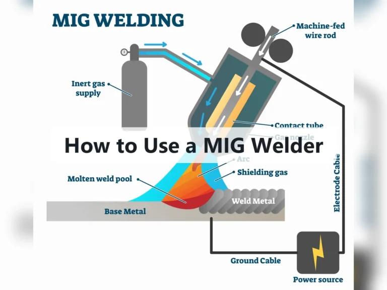
Connecting shielding gas is simple once the cylinder, regulator, hose, and welder fittings match. The gas must travel through a sealed path from the cylinder to the machine’s solenoid and then to the gun nozzle, where it protects the molten weld pool from oxygen and nitrogen in the air.
However a rushed setup can overlook more than a loose fitting The wrong regulator an unsuitable gas an unsecured cylinder excessive flow or a damaged hose can cause. This guide examines “how to connect gas to mig welder” and explains the details that matter in practice.
What should you check when a new argon-carbon dioxide cylinder is sitting beside your welder but you are unsure which port fitting or flow setting to use This.
- ✓Use a regulator and flowmeter rated for the exact shielding gas and cylinder valve connection.
- ✓Secure the cylinder upright, connect the regulator to the cylinder valve, and route the hose to the welder’s gas inlet.
- ✓Leak-test connections with a suitable leak-detection solution before welding.
- ✓Set gas flow while the trigger is activated, and adjust for nozzle size, drafts, and the welding environment.
How to Connect Gas to MIG Welder Components
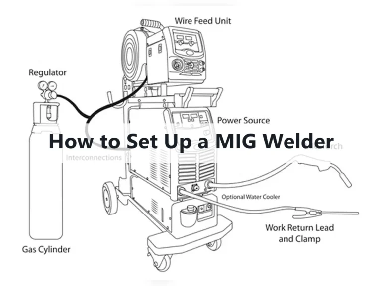
A typical MIG gas system has five essential parts a shielding-gas cylinder a cylinder regulator a flowmeter a gas hose and the welder s gas inlet Some regulators.
The gas path is straightforward: cylinder valve to regulator, regulator outlet to hose, hose to the welder inlet, welder solenoid to the gun liner, and finally the gun nozzle. A problem anywhere along this path can reduce shielding even if the cylinder still contains gas.
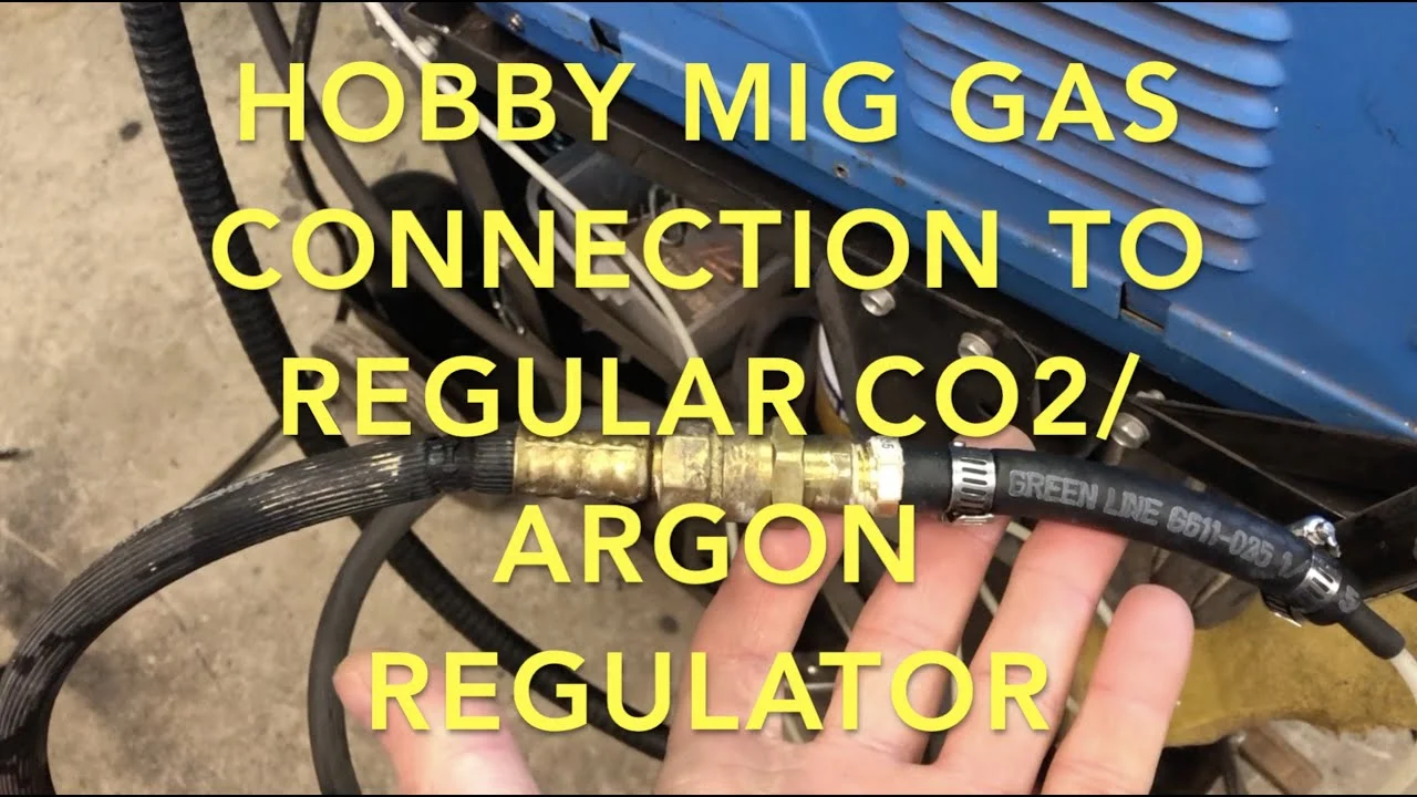
- Cylinder connection: Confirm the regulator’s inlet fitting matches the cylinder valve and gas type.
- Hose connection: Use a hose designed for shielding gas, with clamps or fittings that seal without crushing the hose.
- Welder inlet: Locate the threaded gas-in port on the back or side of the machine; do not connect to an electrical or coolant port.
- Gun path: Make sure the machine’s gas solenoid, gun connection, liner, diffuser, and nozzle are not blocked.
Regulator versus flowmeter
A regulator reduces the high pressure inside the cylinder to a usable delivery pressure A flowmeter then displays the volume of gas reaching the welder commonly in cubic feet per hour or CFH and sometimes liters per minute Many hobby and shop MIG setups use a combination regulator-flowmeter which.
Do not select a regulator based only on whether its threaded inlet appears to fit Regulators are made for particular gases and valve standards In the United States.
Gas inlet and hose requirements
The welder s inlet is usually a small threaded fitting near the rear panel Some machines include a hose barb and clamp others require a female threaded gas.
Never substitute ordinary air hose, fuel hose, or improvised tubing. Shielding-gas hose must be compatible with the gas, pressure, and fittings. Keep it away from hot metal, sharp corners, moving parts, and the path of sparks.
Choose the Right Gas and Hardware Before Connecting
The correct connection begins with the correct gas. Solid-wire MIG welding normally uses an inert or semi-inert shielding gas such as argon, carbon dioxide, or an argon-carbon dioxide blend. Flux-cored wire may be self-shielded and require no cylinder, while gas-shielded flux-cored wire does require external shielding gas.
Check the wire manufacturer’s guidance and the welder’s documentation before opening a cylinder. Gas selection affects arc behavior, penetration, spatter, bead shape, and the risk of porosity. A physically perfect connection cannot compensate for a gas that does not match the wire or material.

- Argon-carbon dioxide blend: A common choice for mild-steel solid wire because it generally provides a smooth arc with manageable spatter.
- Carbon dioxide: Often economical and capable of strong penetration, but it can produce a harsher arc and more spatter than a blend.
- Argon-rich blend: Useful for certain transfer modes and materials, but the blend must match the wire and machine settings.
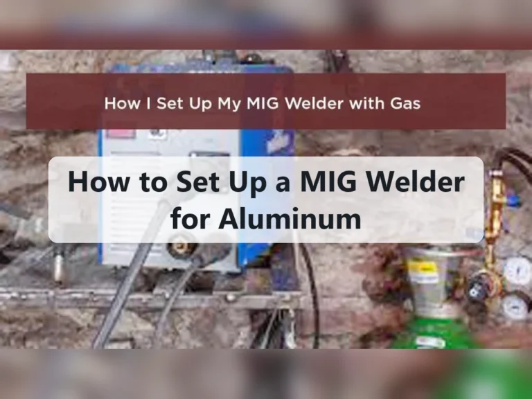
- Pure argon: Common for aluminum MIG applications with the appropriate wire, gun setup, and machine capability; it is generally not the default gas for ordinary steel MIG welding.
Match the regulator to the cylinder
Use only a regulator labeled for the gas being used The connection may be intentionally different between gases to reduce the chance of an incorrect hookup Never use.
Inspect the regulator before installing it Look for a readable gauge or flow tube an undamaged inlet nipple a clean sealing surface and a control knob that turns.
Understand cylinder labels and contents
Read the cylinder label instead of relying on paint color. Cylinder colors are not a dependable substitute for identification, especially when cylinders come from different suppliers or have been repainted. The label should identify the gas, and the cylinder should be in date and suitable for service through a legitimate gas supplier.
Do not connect oxygen, acetylene, propane, compressed air, or an unidentified cylinder to a MIG shielding-gas system. Oxygen is particularly dangerous around oil, grease, and combustible materials, and it is not a substitute for MIG shielding gas. This distinction matters when answering “how to connect gas to mig welder”.
Prepare the work area
Place the cylinder upright on a stable surface and secure it with a chain, strap, or the welder’s approved cylinder holder. The cylinder must not be left where it can fall, roll, block an exit, or be struck by the workpiece. Keep it away from direct heat, open flames, and heavy traffic.
Provide ventilation suitable for the welding process. Shielding gas can displace breathable air, especially in pits, tanks, small rooms, and other confined spaces. Do not treat a gas cylinder as a portable air source, and do not weld in a confined space without an appropriate safety plan and atmospheric controls.
Step-by-Step: How to Connect Gas to MIG Welder
Once the components are confirmed, the physical connection can be completed in a controlled sequence. Keep the cylinder valve closed during assembly, turn the welder off, and keep the gun trigger away from anything that could accidentally activate it.
Use the cylinder’s protective cap whenever the regulator is not installed. A cylinder valve can release dangerous force if damaged, so handle the cylinder by its body and valve protection—not by the regulator, hose, or cap.
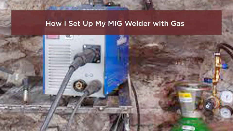
- Keep it upright: Secure the cylinder before removing the protective cap or opening the valve.
- Use the right tools: Tighten the regulator connection with the appropriate wrench; do not use pliers that can damage the fitting.
- Do not use sealant casually: Use only the sealing washer, O-ring, or fitting method specified for the connection.
- Open slowly: Stand to the side of the regulator and open the cylinder valve gradually.
- Turn off and inspect the welder. Switch the machine off and unplug it when the manual or local procedure calls for disconnection. Locate the gas inlet and remove dust or debris from the area without pushing contamination into the fitting.
- Secure the cylinder. Set the cylinder upright in its holder and fasten it so it cannot tip. Remove the protective cap only when you are ready to install the regulator.
- Verify the regulator. Confirm that the regulator is rated for the gas and that its inlet connection matches the cylinder valve. Check whether the regulator requires a sealing washer, and install a new suitable washer if the old one is damaged or missing.
- Attach the regulator. With the cylinder valve closed, thread the regulator onto the valve by hand first. The threads should engage smoothly. If they do not, stop and verify the connection; never force or cross-thread it.
- Tighten the connection. Use the correct wrench to make the connection secure according to the regulator or supplier instructions. Do not overtighten, because excessive force can damage the valve, fitting, or sealing washer.
- Connect the gas hose. Attach one end of the approved hose to the regulator outlet. Connect the other end to the welder’s gas inlet, using the specified barb, clamp, threaded fitting, washer, or O-ring. Keep the hose routed neatly and protected from heat.
- Close the flow control. Turn the flow adjustment knob toward the closed position before pressurizing the system. The exact control direction varies, so use the markings or manual rather than assuming.
- Open the cylinder valve slowly. Watch the high-pressure gauge as the cylinder pressurizes. If you hear a sustained hiss, see damage, or observe an abnormal gauge response, close the valve and investigate before continuing.
- Pressurize and leak-test. Apply a commercially suitable leak-detection solution to the cylinder connection, regulator joints, hose fittings, and welder inlet. Bubbles that continue growing indicate a leak; close the cylinder and repair the connection before welding.
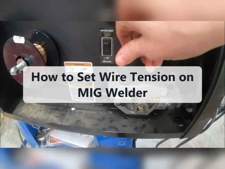
- Set the flow. Turn on the welder, activate the gun trigger, and adjust the flowmeter while gas is actually flowing. Set the initial rate according to the wire, nozzle, material, and manufacturer guidance.
- Check the gun. Gas should exit the nozzle when the trigger is pressed. If the wire feeds but no gas flows, stop and diagnose the solenoid, hose, liner, diffuser, nozzle, or flow control before welding.
Why the trigger must be activated during flow adjustment
The flowmeter reading is meaningful when gas is moving through the system. A static reading can be misleading because the hose and regulator may be pressurized while the solenoid is closed. With the trigger pressed, the gas path is open and the flowmeter shows the operating condition more accurately.
Use a safe way to activate the trigger according to the machine’s instructions. Keep the gun pointed away from people and conductive surfaces, and remember that the wire may feed when the trigger is pressed.
Set MIG Shielding-Gas Flow Correctly
Many indoor MIG applications begin around 20 to 30 CFH, which is approximately 9 to 14 L/min, but there is no universal setting. The appropriate flow depends on nozzle size, welding current, wire diameter, joint shape, gas type, travel speed, and air movement.
Too little gas allows surrounding air to contaminate the weld pool. Too much gas can create turbulence that draws air into the shielding envelope, wastes cylinder contents, and may produce the same porous result as insufficient flow. The goal is stable coverage, not the highest number on the flowmeter.
- Start within the recommended range: Use the wire and machine guidance as the baseline instead of guessing from cylinder pressure.
- Watch the environment: Doors, fans, compressed-air lines, and outdoor breezes can strip shielding from the weld.
- Keep the nozzle clear: Spatter buildup changes the gas pattern and can restrict flow.
- Adjust in small increments: Change one factor at a time, then inspect a test weld for porosity and arc behavior.
Indoor versus outdoor welding
Standard MIG shielding gas is easily disturbed outdoors. Even a light breeze can carry away the gas around the arc, leaving pinholes and a rough, contaminated bead. A windbreak may help, but it must be noncombustible and positioned so it does not trap dangerous fumes or interfere with safe access.
Increasing flow dramatically is not a reliable solution to wind. If the work must be performed in moving air, consider whether a suitable self-shielded flux-cored process is more appropriate, provided the machine and wire support it.
Gas flow and nozzle condition
The nozzle directs shielding gas around the wire and arc. Spatter inside the nozzle can narrow the opening, disturb the flow, or partially block the gas. Clean the nozzle with tools intended for that purpose, and replace it if it is severely distorted or damaged.
Keep these limitations in mind when considering “how to connect gas to mig welder”.
Maintain the correct contact-tip position and nozzle-to-work distance for the wire and transfer mode. Holding the gun too far away can move the arc outside the effective shielding envelope even when the flowmeter is set correctly.
Leak Testing, Shutdown, and Cylinder Handling
A leak may be small enough to escape notice but large enough to empty a cylinder overnight It can occur at the cylinder connection regulator outlet hose end.
Use a commercial leak-detection solution compatible with the equipment. Brush it around each joint while the system is pressurized, then watch for expanding bubbles. Wipe the solution away afterward if the equipment instructions require it.
- After each connection: Test the regulator inlet, outlet, hose ends, and welder inlet.
- Before storage: Close the cylinder valve rather than relying only on the regulator knob.
- For longer shutdowns: Bleed pressure from the downstream hose as directed, then return controls to their recommended positions.
- During inspection: Replace cracked hoses, damaged washers, leaking regulators, and unreadable gauges.
Correct shutdown sequence
When welding is finished, release the gun trigger and close the cylinder valve. Allow the machine or system to depressurize according to its instructions, then turn the regulator adjustment back as recommended. Closing the cylinder valve is important because leaving it open keeps the entire hose and regulator system under pressure.
If the welder will be moved, disconnect the gas supply safely and reinstall the cylinder cap. Keep the cylinder secured during transport, use a suitable cart, and never drag, roll, or lift it by the valve or regulator.
Common Connection Mistakes and What They Cause
Most gas-related MIG defects come from a small number of setup errors. Identifying the likely cause saves time because changing wire speed or voltage will not correct a blocked nozzle or empty cylinder.
- Wrong regulator: A mismatched gas connection can leak, fail to seal, or be unsafe to operate.
- Loose hose fitting: Gas escapes before reaching the gun, often causing low flow and rapid cylinder loss.
- Excessive flow: Turbulence can pull surrounding air into the shielding zone.
- Open cylinder with machine off: The system may leak unnoticed while consuming gas.
| Symptom | Likely gas-related causes | Useful first checks |
|---|---|---|
| Porosity or pinholes | Low flow, empty cylinder, wind, leak, contaminated material, blocked nozzle | Check cylinder contents, trigger flow, hose joints, nozzle, and work area |
| No gas at the nozzle | Closed valve, closed flow control, failed solenoid, kinked hose, blocked diffuser | Listen for the solenoid, inspect the hose, and confirm flow with the trigger pressed |
| Gas runs out quickly | Leaking fitting, cylinder valve left open, excessive flow, damaged hose | Leak-test the complete system and compare the flow setting with the recommended range |
| Unstable arc or heavy spatter | Incorrect gas, poor flow, turbulence, wrong polarity, dirty nozzle | Verify gas and wire compatibility, then inspect the gas path and gun |
When the flowmeter reading looks normal
A normal flowmeter reading does not prove that gas reaches the arc. The nozzle may be blocked, the diffuser may be clogged, the gun connection may not seal, or the hose may collapse internally. Check the system from the cylinder toward the nozzle instead of replacing welding settings at random.
Also inspect for drafts at the workpiece. A machine can deliver the correct flow at the nozzle while outside air removes the gas before it protects the weld pool.
When the regulator freezes or behaves strangely
Rapid gas expansion can cool a regulator, particularly during high demand or when carbon dioxide is used. Frost or abnormal regulator behavior is a reason to stop and consult the gas supplier or equipment instructions. Do not heat the regulator with an open flame, heat gun, or other improvised method.
If a gauge is damaged, sticks, or does not return to a believable reading, remove the regulator from service. Pressure equipment should be repaired or replaced through an appropriate supplier rather than opened casually.
FAQ: Connecting Shielding Gas to a MIG Welder
Can any gas cylinder connect to a MIG welder?
No. The cylinder must contain a gas suitable for the wire and process, and its valve must match a compatible regulator. Do not use an unidentified cylinder or force a fitting with an improvised adapter.
Does a MIG welder need gas for every type of wire?
No. Solid MIG wire requires external shielding gas, and gas-shielded flux-cored wire does as well. Self-shielded flux-cored wire is designed to create its own shielding and normally does not use a cylinder.
Where does the gas hose connect on a MIG welder?
It connects to the machine’s marked gas inlet, usually on the rear or side panel. The other end connects to the regulator or flowmeter outlet. Confirm the fitting style in the machine manual before tightening anything.
How much gas flow should a MIG welder use?
A common starting range for indoor work is about 20 to 30 CFH, or roughly 9 to 14 L/min, but the correct value depends on the gas, nozzle, wire, current, and surrounding airflow. Adjust while the trigger is activated and gas is flowing.
Can I use a regulator made for argon with carbon dioxide?
Use a regulator specifically rated and fitted for the gas in the cylinder. Argon and carbon dioxide commonly use different CGA connections in the United States, and a regulator that appears similar may not be safe or compatible.
Why is gas flowing at the regulator but not at the gun?
Possible causes include a closed machine flow control, a kinked hose, a blocked nozzle or diffuser, a failed solenoid, or a poor gun connection. Disconnect power as appropriate, inspect the gas path, and follow the welder’s troubleshooting instructions.
Should the cylinder valve stay open when the welder is not being used?
No. Close the cylinder valve whenever welding is finished or the system will be unattended. For extended storage, follow the machine and gas supplier’s shutdown procedure and protect the cylinder from tipping or damage.
Conclusion
Learning how to connect gas to mig welder equipment comes down to matching the gas and regulator securing the cylinder making a sealed hose connection testing for leaks.
Stop immediately if a fitting leaks, a regulator is damaged, a cylinder is unidentified, or gas behavior seems abnormal. Shielding gas is compressed equipment, and safe handling matters as much as weld appearance.
Before welding, verify the gas label and regulator match, secure the cylinder, leak-test every connection, and confirm steady flow at the nozzle with the trigger pressed.