How to Fix a MIG Welder: Problems, Causes, and Helpful Solutions
To fix a MIG welder, identify whether the fault involves power, wire feeding, shielding gas, the welding circuit, or the gun, then test one cause at a time.
A small detail often changes the diagnosis a welder that powers on is not necessarily producing a usable welding arc The display fan and indicator lights may work.
Before replacing parts note exactly what happens when you pull the trigger Does the wire feed but no arc appear Does the machine click without feeding wire Is. This guide examines “how to fix a mig welder” and explains the details that matter in practice.
This guide explains how to fix a MIG welder by starting with safe basic checks and progressing to wire-feed gas electrical gun and arc-quality problems You will learn.
- ✓Disconnect power before inspecting internal parts, and never bypass a fuse, ground, interlock, or circuit breaker.
- ✓Most poor MIG performance comes from incorrect settings, contaminated material, weak grounding, restricted wire feed, or inadequate shielding gas.
- ✓Wire-feed symptoms should be diagnosed separately from arc, gas-flow, and power-supply symptoms.
- ✓Replacing the contact tip, liner, nozzle, or ground clamp can solve many problems, but repeated breaker trips and burnt electronics require professional service.
Start With Safety and a Symptom Check
A MIG welder combines mains electricity stored electrical energy hot metal compressed gas and an exposed arc Even after the machine is switched off capacitors inside some welders.
Move the workpiece to a dry well-ventilated area remove flammable materials wear a welding helmet and appropriate protective clothing and secure the gas cylinder upright Disconnect the welder.
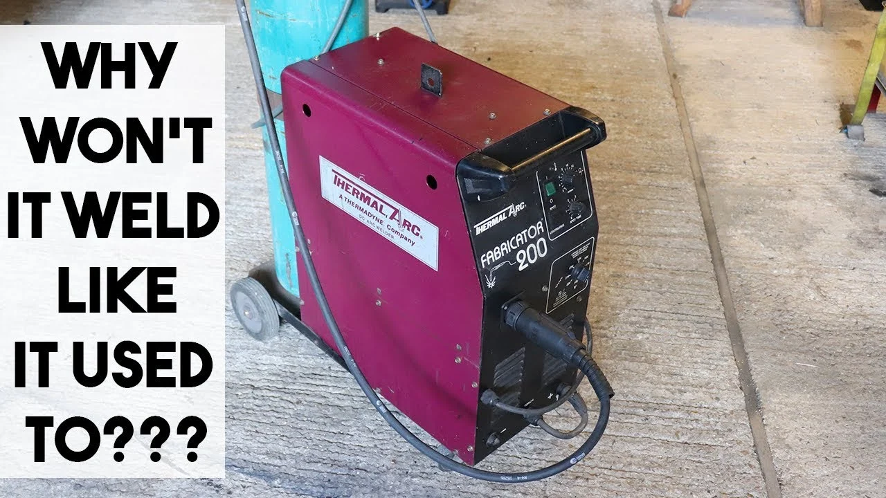
- Power isolation: Unplug the machine or open its disconnect before changing consumables or inspecting connections.
- Gas handling: Keep the cylinder secured, inspect the regulator and hose, and never use oil or grease on oxygen-related equipment.
- Ventilation: Welding fumes can be hazardous, especially on galvanized, painted, coated, or unknown metals.
- Internal faults: Leave energized circuit-board, capacitor, and mains-side repairs to a qualified service professional.
Write down the symptom before making a change. “It will not weld” is too broad; “the wire feeds continuously, but there is no arc when the wire touches clean steel” points toward the welding circuit, ground path, contact tip, or output connection.
What the trigger response tells you
| What happens when the trigger is pressed | Likely areas to inspect first |
|---|---|
| Nothing happens | Input power, fuse or breaker, trigger circuit, gun connector, machine switch, or internal control fault |
| Gas flows, but wire does not move | Drive system, spool tension, liner, trigger control, motor, or jammed wire |
| Wire moves, but there is no arc | Ground clamp, work lead, contact tip, output connection, polarity, or power-stage fault |
| Arc starts but stutters | Feed restriction, dirty tip, poor ground, wrong settings, contaminated wire, or inadequate gas coverage |
| Arc is acceptable but weld is porous | Gas leak, empty cylinder, blocked nozzle, excessive airflow, contamination, or incorrect gas flow |
| Breaker trips or smoke appears | Overload, short circuit, damaged cable, incorrect supply, overheating, or internal failure |
How to Fix a MIG Welder That Has No Power or No Arc
When the machine does not respond begin at the power source and work toward the welding circuit Do not assume a dead display means the welder itself has.
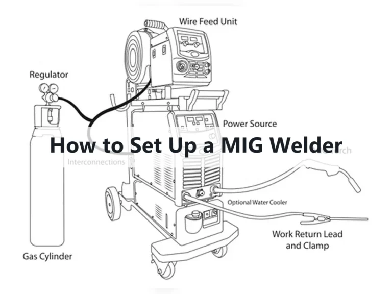
If the display works but the arc does not the fault is farther downstream A MIG welder needs a complete circuit current leaves through the gun and wire.

- Confirm the supply: Test the receptacle with an appropriate method and verify that the welder’s input requirement matches the available voltage.
- Inspect the return path: Clamp directly to clean, bare metal rather than rust, paint, scale, or a loose welding table connection.
- Check polarity: Match gun and work-lead connections to the wire and shielding-gas process being used.
- Look for heat damage: Discolored plugs, loose terminals, melted insulation, or a hot connector indicate a problem that needs correction before welding.
If the welder is completely dead
Reset the breaker once, after confirming that no other high-load equipment is sharing the circuit. If it trips again immediately, stop. Repeated resets can worsen a short circuit or create a fire hazard.
Inspect the power cord plug switch and visible strain relief for cuts crushed sections loose blades or overheating Do not replace a fuse with a larger rating defeat.
Some welders include thermal protection If the unit shut down after extended welding allow it to cool with its ventilation openings clear A thermal light or fan behavior.
If the machine powers on but will not strike an arc
Turn off the welder and inspect the work lead where it enters the machine Check that the connector is fully seated and that the cable has no severe.
Clean the contact area on the workpiece with a wire brush or grinder using suitable eye and face protection Paint rust mill scale and oily residue can interrupt.
Next inspect the gun s contact tip The tip must fit the wire diameter and should not be loose burned or clogged with spatter A tip that is.
Verify the gun and work-lead polarity against the wire type and the machine s instructions Solid wire with shielding gas and self-shielded flux-core wire may use different polarity.
How to Fix a MIG Welder With Wire-Feed Problems
Wire-feed faults are among the most common MIG problems because the system has several friction points the spool hub drive rolls inlet guide liner contact tip and gun.
First release trigger pressure switch off the machine and cut away damaged wire Do not pull a tangled bird s nest through the gun that can kink the.
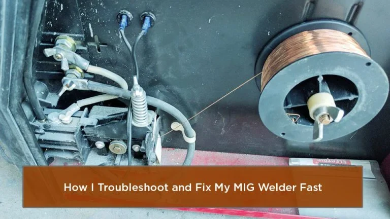
- Spool drag: The spool should unwind smoothly without continuing to spin freely after the trigger is released.
- Drive-roll match: Use the groove designed for the wire diameter and type; a mismatched roll can slip or deform the wire.
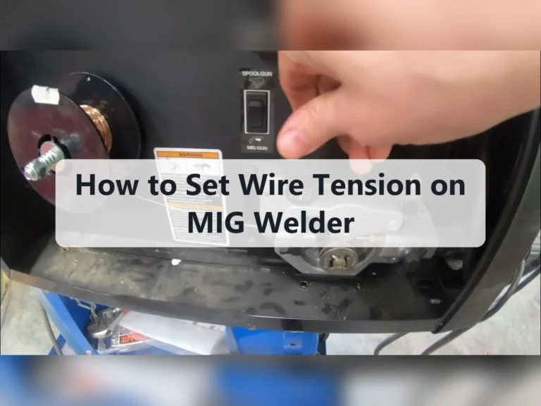
- Pressure setting: Tighten the tension only enough to feed consistently; excessive pressure can flatten wire and increase liner friction.
- Gun path: Keep the cable reasonably straight while testing because sharp bends make restricted liners appear worse.
Wire does not feed at all
Listen when the trigger is pressed. If the gas solenoid clicks but the motor is silent, check the trigger connection, gun plug, and visible motor wiring with power disconnected. A failed trigger switch, motor, control relay, or circuit board can cause this symptom.
If the motor can be heard but the wire stays still inspect the drive-roll release mechanism The roll may not be applying pressure the wire may not be.
A blocked contact tip can also stop the wire at the end of the system Remove the tip and briefly test feed only when it is safe and.
Wire slips, surges, or bird-nests
Wire slipping often produces a popping arc because the welder alternates between feeding too little and catching up Clean spatter from the drive rolls with an appropriate brush.
Bird-nesting usually occurs between the drive rolls and the liner Common causes include too little roll tension a blocked inlet a sharp gun bend an incorrect liner or.
Use wire from a dry, clean spool. Moisture and corrosion increase friction and can contaminate the weld. Store opened wire in a dry location and avoid touching it unnecessarily with dirty or wet gloves.
When the liner or contact tip is the problem
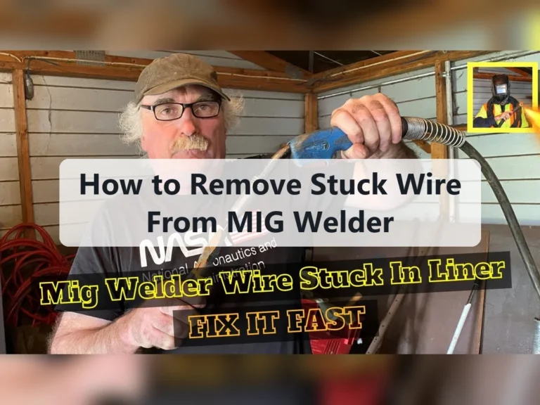
The liner guides the wire through the gun cable. It can collect dust, rust, and shavings or become kinked near the gun neck and machine connector. Symptoms include inconsistent feeding, increased motor noise, and repeated bird-nests even after the drive system is adjusted.
Replace the liner with the correct type and length for the gun and wire size Follow the gun manufacturer s fitting instructions because a liner that is too. This distinction matters when answering “how to fix a mig welder”.
For aluminum wire, use equipment designed for aluminum feeding, often including a suitable liner, drive rolls, and gun setup. Aluminum is softer than steel and is more likely to buckle in a conventional steel-wire path.
Shielding Gas, Porosity, and Spatter Problems
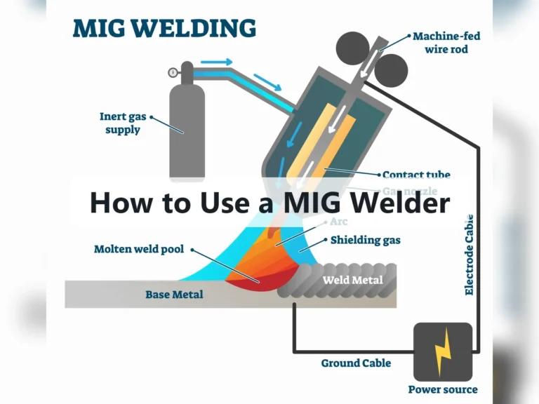
Shielding gas keeps atmospheric oxygen and nitrogen away from the molten weld pool If the gas does not reach the joint correctly the weld may contain pinholes bubbles.
Confirm that the cylinder contains gas and that the regulator is connected correctly. With the cylinder valve open, check the hose, fittings, solenoid area, and gun connection for leaks using a suitable leak-detection method. Never use a flame to search for leaks.
- Porous weld face: Suspect lost gas coverage, contamination, excessive airflow, or a blocked nozzle.
- No gas sound: Check the cylinder valve, regulator, solenoid, trigger circuit, and hose for restrictions or failure.
- Gas but poor protection: Look for leaks, a damaged nozzle, incorrect flow, wind, or an excessive gun-to-work distance.
- Heavy spatter: Check polarity, wire condition, settings, stickout, grounding, and gas selection rather than blaming flow alone.
Check the nozzle and gas diffuser
Spatter can build inside the nozzle and partially block gas flow Turn off the machine allow hot parts to cool and clean or replace the nozzle when its opening is restricted or badly damaged Inspect the diffuser and tip.
Keep the nozzle at a consistent distance from the work and avoid dragging it through the weld pool. A long electrical stickout or an awkward gun angle can expose the arc to air even when the regulator indicates flow.
Use flow settings thoughtfully
Gas flow that is too low may fail to shield the puddle, while excessive flow can create turbulence that draws air into the shielding envelope. Use the range recommended for the machine, gas, nozzle, wire, and environment rather than assuming more gas is always better.
Outdoor airflow is a major limitation. A fan, open garage door, or strong breeze can disperse shielding gas. Move indoors when practical or use an appropriate wind barrier, while maintaining safe ventilation and avoiding an enclosed area where fumes can accumulate.
Fix Poor Weld Quality by Separating Settings From Hardware
Once power feeding and gas delivery are confirmed adjust the welding variables A MIG power source generally pairs wire-feed speed with voltage or an arc-length control Wire speed.
Use the chart on the welder or wire package as a starting point for material thickness wire diameter gas and joint type Test on clean scrap made from.
- Changing everything: Adjusting voltage, wire speed, gas, travel speed, and stickout together hides the original cause.
- Ignoring preparation: Oil, paint, rust, and mill scale can create defects that settings cannot correct.
- Long stickout: Holding too much wire beyond the contact tip reduces effective heating and changes arc behavior.
- Wrong travel speed: Moving too slowly can create a wide, overheated bead; moving too quickly can cause poor fusion or an undersized bead.
Symptoms of incorrect wire speed and voltage
| Symptom | Possible cause | Useful check |
|---|---|---|
| Wire repeatedly pushes the gun away | Wire speed too high, voltage too low, or restricted contact tip | Check feed path and increase voltage or reduce wire speed in small increments |
| Long, wandering arc with weak penetration | Voltage too high, wire speed too low, or excessive stickout | Return to the material chart and shorten stickout |
| Sharp popping and erratic starts | Incorrect balance of voltage and wire speed, poor ground, or contamination | Clean the joint and connections before tuning settings |
| Large, cold-looking bead | Travel too slow, voltage or wire speed unsuitable, or insufficient joint preparation | Check heat input and travel technique on scrap |
| Undercut at the edge | Excessive heat, fast travel, excessive voltage, or poor angle | Reduce heat or adjust speed and gun position gradually |
Inspect the material and technique
Clean the joint until bright, sound metal is visible where practical. Fit-up matters too: a large gap, poor bevel, or contaminated backing can make a properly functioning welder appear defective. For coated or galvanized material, follow appropriate preparation and fume-control practices.
Maintain a consistent travel angle, work angle, and stickout. Keep the gun close enough for stable shielding without allowing the nozzle to contact the puddle. If the bead looks acceptable on scrap but fails on the project, reassess joint access, material condition, and heat dissipation.
Gun, Cable, Trigger, and Connection Faults
The gun assembly experiences heat flexing spatter and repeated handling A loose gun connector can interrupt both the trigger circuit and wire path while a damaged cable can.
Check that the gun plug is fully inserted and secured. Examine the trigger for sticking, delayed response, or an inconsistent click. Do not continue using a trigger that remains engaged after release; that can cause unintended wire and gas operation.
- Connector seating: A partially inserted gun connector can cause both trigger and feeding symptoms.
- Cable bends: Tight loops and crushed sections increase liner friction and may damage conductors.
- Neck condition: A loose or overheated gun neck can affect contact-tip alignment and gas coverage.
- Ground cable: Flexing damage and hot spots indicate resistance in the return circuit.
If gently moving the gun cable changes the symptom, suspect a damaged liner, conductor, or connection. Avoid testing by flexing an energized cable aggressively. Replace damaged gun parts with compatible components rather than improvising electrical repairs.
Some machines use a removable spool-gun or specialty-gun connector. Confirm that the selected gun mode, if present, matches the connected equipment. A control setting intended for a different feeder can make the trigger appear dead or cause unexpected operation.
When Replacement or Professional Repair Is the Right Choice
Consumables are normal maintenance items contact tips nozzles liners drive rolls and sometimes diffusers Replacing them is reasonable when inspection shows wear blockage deformation or incompatibility Keep the.
Internal components are different Control boards rectifiers transformers inverter modules capacitors relays and mains wiring can expose you to lethal voltage and expensive secondary damage A machine that.
- Owner-level fix: Cleaning the workpiece, replacing a tip, correcting polarity, reseating a connector, or adjusting feed tension.
- Service-level diagnosis: Testing a motor, solenoid, trigger circuit, rectifier, control board, or output stage.
- Stop immediately: Burning odor, visible arcing inside the case, melted conductors, repeated fuse failure, or electric shock.
- Cost comparison: Consider parts availability, machine age, duty-cycle history, and repair labor before replacing a major module.
Before requesting service, record the model, input voltage, wire type and diameter, exact symptom, and what you already tested. A short video of the trigger response or an image of the weld can help a technician reproduce the issue, provided the recording is made safely.
Preventive Maintenance That Reduces MIG Failures
Good maintenance prevents many situations in which people search for how to fix a MIG welder. Keep the machine’s ventilation openings clear and remove accumulated dust according to the manufacturer’s maintenance instructions. Do not blow debris deeper into sensitive electronics with uncontrolled compressed air.
Inspect the gun, work lead, plug, gas hose, regulator, and ground clamp before demanding jobs. Replace damaged consumables early rather than forcing the drive system to compensate for them. Store wire in a dry environment and protect the cylinder and regulator from impact.
- Before welding: Confirm polarity, wire size, gas supply, ground contact, and consumable condition.
- During use: Watch for unusual motor noise, hot connectors, unstable feeding, or changes in arc sound.
- After welding: Remove spatter from the nozzle, release spool tension as appropriate, and coil cables without sharp bends.
- Periodically: Inspect drive rolls, liner, power cord, duty-cycle behavior, and ventilation openings.
Do not exceed the welder’s duty cycle. Long periods at high output can activate thermal protection or shorten component life. Let the machine cool when required, and keep the fan and vents unobstructed while it operates.
Frequently Asked Questions
Why does my MIG welder feed wire but not create an arc?
Check the work clamp, clean return path, polarity, contact tip, gun connector, and output connections first. If these are sound and there is still no arc, the machine may have an internal output or control fault that needs professional testing.
Why does my MIG welder keep bird-nesting wire?
Bird-nesting usually results from inadequate drive-roll tension, a blocked or damaged liner, excessive gun bending, a wrong drive-roll groove, or a jammed contact tip. Remove the tangled wire, inspect the entire feed path, and use only enough tension to feed smoothly.
Can a bad ground clamp make a MIG welder stop working?
Yes. A loose, rusty, contaminated, or damaged ground clamp can prevent arc starting or cause popping and instability. Clamp directly to clean metal close to the weld and inspect the work lead for heat damage or broken strands.
Why is my MIG weld porous even though gas is flowing?
Gas can flow at the regulator while coverage is still inadequate at the arc. Check for leaks, wind, a blocked nozzle, excessive flow turbulence, long stickout, contaminated material, and an incorrect gun angle.
Should I replace the MIG liner or contact tip first?
Replace the contact tip first when it is visibly worn, blocked, loose, or fused with spatter because it is inexpensive and easy to isolate. Suspect the liner when feeding remains inconsistent with a clean, correctly sized tip and properly adjusted drive system.
Why does the breaker trip when I pull the trigger?
A shorted output, damaged cable, incorrect input supply, overloaded circuit, or internal component failure can trip the breaker. Reset it only once after a basic inspection; repeated trips require disconnection and qualified diagnosis.
Can I repair a MIG welder myself?
You can usually handle external setup and consumable issues, such as cleaning connections, replacing a nozzle, correcting wire tension, or changing a contact tip. Internal electrical repairs are unsafe without the appropriate training, test equipment, and manufacturer-specific service information.
Conclusion
The most reliable way to fix a MIG welder is to follow the symptom from the outside in verify safe power inspect the ground and polarity confirm wire.
Do not overlook the limits of owner troubleshooting. Repeated breaker trips, internal arcing, smoke, burnt wiring, and failed power electronics are safety issues, not adjustment problems. Stop using the machine and arrange qualified service when those signs appear.
Disconnect the welder, write down its exact trigger symptom, and inspect the ground clamp, contact tip, wire path, and gas supply before changing any settings.
The answer to “how to fix a mig welder” should be applied with these conditions and limitations in mind.