How to Feed Wire Into a MIG Welder: Step-by-Step Instructions
Install the correct spool, thread the wire through the guide and drive rolls into the liner, then set tension just high enough for smooth feeding.
Feeding wire into a MIG welder is straightforward once the wire path is clear the drive-roll groove matches the wire and the spool is loaded in the correct.
The counterintuitive part is that tighter is not automatically better Drive-roll pressure that seems helpful can deform soft aluminum wire flatten solid steel wire or make a bird. This guide examines “how to feed wire into a mig welder” and explains the details that matter in practice.
This guide explains how to feed wire into a MIG welder from spool selection through final testing You will learn the correct loading sequence how to set the.
- ✓Match the wire size, material, drive-roll groove, liner, and contact tip before feeding wire.
- ✓Keep the spool from over-running, but use only enough brake tension to stop freewheeling.
- ✓Start with moderate drive-roll pressure and increase it only until the wire feeds consistently.
- ✓Remove the contact tip when testing a difficult feed path or clearing a suspected obstruction.
- ✓Never bypass gun, trigger, grounding, or electrical safety precautions while troubleshooting.
How to Feed Wire Into a MIG Welder
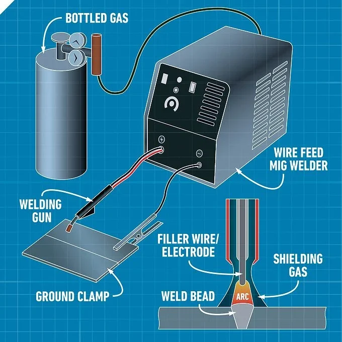
A MIG welder moves wire through a series of connected components rather than pushing it directly from the spool to the workpiece The wire travels from the spool.
Each part has a specific job The spool stores the wire the brake controls its momentum the drive rolls provide forward force the liner supports and guides the.
- Wire compatibility: Confirm the wire diameter and material match the liner, drive-roll groove, contact tip, and machine settings.
- Feed direction: The spool should unwind from the bottom or the direction shown by the machine’s guide, not pull over the top unless the design specifies it.
- Clear path: Keep the wire aligned with the inlet guide and drive rolls so it does not rub sharply against the feeder housing.
- Gun condition: A kinked cable, blocked liner, or oversized contact tip can interrupt an otherwise correct setup.
What the drive rolls actually do
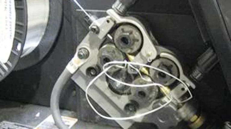
The drive rolls squeeze the wire between rotating surfaces One roll may be powered while the other applies pressure or both may be powered depending on the feeder.
Knurled rolls can help move flux-cored wire because their toothed surface grips the wire but they can damage solid wire by marking it and creating debris Use the.
Why the contact tip matters
The contact tip should have the correct internal diameter for the wire A tip that is too tight.
The tip is not supposed to compensate for a damaged liner or excessive drive-roll pressure. If wire will not pass through a correctly sized tip with reasonable force, stop and inspect the path instead of forcing it.
Prepare the MIG Welder Before Loading Wire
Preparation prevents most feeding problems Before opening the side panel identify the wire you plan to use and check the label for its diameter material and recommended polarity.
Disconnect the welding power when the machine s instructions require it and keep the gun pointed away from yourself and anyone nearby The wire can leave the contact.
- Disable accidental feeding: Turn the welder off or disconnect power according to the manufacturer’s procedure before changing the spool or drive rolls.
- Protect your hands: Wear gloves when handling cut wire, but keep loose clothing and fingers away from rotating rolls.
- Prevent unwanted arcs: Do not allow the exposed wire to touch the workpiece, grounded metal, or another conductive object during testing.
- Secure the gun: Hold or place the gun so the nozzle and wire point in a safe direction.
Inspect the consumables
Remove the nozzle and look at the contact tip If the opening is blocked with spatter visibly enlarged burned or damaged replace it with a tip marked for.
Check the liner at the rear of the gun if the design makes it accessible A liner that is sharply bent contaminated with metal dust or worn at.
Verify the spool and wire
Use a spool that fits the hub and does not contact the side panel The retaining nut or spool retainer should hold the spool securely while allowing it.
Keep the factory wire tie or retaining clip in place until the spool is installed Once released the wire can spring loose and form crossed loops that later.
Step-by-Step: Loading and Feeding MIG Wire
The exact feeder layout varies, but the sequence is similar on most compact and shop MIG machines. If the welder’s manual shows a different spool direction, roll arrangement, or tension system, follow that machine-specific instruction.
The goal is to create a smooth, supported path from the spool to the gun. Do not use the drive motor to force wire through a closed lever, misaligned guide, or obstructed liner. Correct the mechanical problem first.
- Start with the gun straight: Lay the cable in a broad, relaxed curve to minimize liner friction.
- Cut a clean point: Clip the wire end squarely or at a slight angle, then remove sharp hooks and burrs.
- Use moderate pressure: Set the drive-roll tension low enough to avoid crushing the wire.
- Test in stages: Feed through the rolls first, then through the liner, and finally through the contact tip.
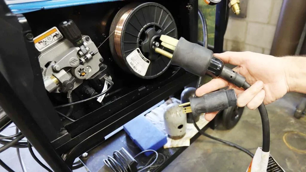
- Turn off and prepare the machine. Switch off the welder and follow its power-isolation instructions. Open the feeder cover, remove an empty spool if necessary, and locate the inlet guide, drive-roll release, and tension adjustment.
- Install the new spool. Place the spool on the hub so the wire unwinds in the direction indicated by the feeder. Fit the retainer and make sure the spool turns without side-to-side wobble.
- Set the spool brake. Adjust the hub brake so the spool stops shortly after you stop pulling wire. It should not coast freely, but it also should not require excessive force to turn.
- Select the correct drive-roll groove. Match the groove marking to the wire diameter. Flip or replace the roll if the required groove is not currently facing the wire.
- Release the pressure arm. Lift the tension arm or open the drive-roll assembly. This creates a clear channel for inserting the wire and prevents the rolls from scraping the wire during insertion.
- Cut the wire end cleanly. Hold the spool so it cannot unwind, remove the retaining clip, and cut off the bent end. Keep your fingers clear of the sharp point.
- Guide the wire into the inlet. Insert the wire through the guide tube and into the first drive-roll channel. Keep the wire aligned with the center of the groove.
- Pass the wire through the rolls. Continue the wire through the outlet guide toward the gun liner. Confirm that it sits in the groove rather than on top of the roll or against its edge.
- Close the pressure arm lightly. Lower the arm and turn the tension knob until the rolls grip the wire. Do not begin with maximum tension.
- Feed the wire through the liner. If the gun is attached, straighten the cable and press the feed or trigger control as directed by the machine. Guide the wire gently rather than pushing hard into resistance.
- Install or verify the contact tip. Once the wire reaches the front of the gun, cut the protruding end, install the correctly sized tip, and pass the wire through it. Refit the nozzle after checking for smooth movement.
- Trim the wire and test. Leave a suitable short stick-out for starting, then feed a small amount while holding the gun safely. Watch for smooth, steady movement and listen for drive-roll slipping.
How to set drive-roll tension correctly
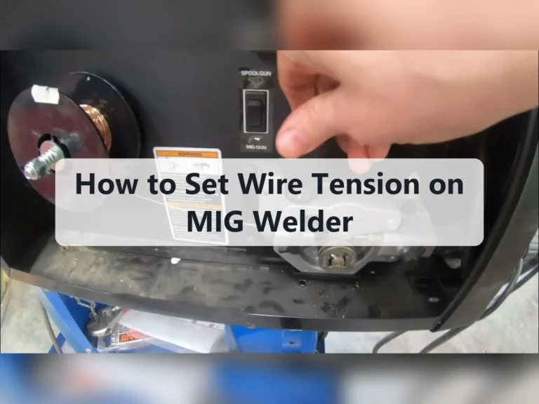
Drive-roll tension should be high enough to move the wire but low enough that the wire is not flattened A practical check is to feed the wire toward.
Do not perform this test with the wire pointed at your hand and follow the welder s instructions for the feed mode If the wire slips with light.
When to remove the contact tip during loading
Removing the contact tip makes initial feeding easier because the wire does not have to pass through a small opening while the liner is being tested It is.
With the tip removed, keep the gun pointed safely and prevent the live wire from touching grounded metal. Once the wire exits the gun smoothly, install a clean tip of the correct size and test again.
Adjust the Spool Brake, Liner, and Contact Tip
A good wire feed depends on balanced resistance The drive rolls need enough grip to pull the wire but the spool brake liner and contact tip should offer.
When deciding how to feed wire into a MIG welder pay particular attention to what happens between the drive rolls and the nozzle The wire may appear to.
- Liner size: The liner should suit the wire diameter and material; a steel liner used for soft aluminum can create unnecessary drag.
- Contact tip fit: The marking on the tip should match the wire size, not merely look close enough.
- Cable position: Avoid tight loops and sharp bends while feeding or welding.
- Hub resistance: The spool must rotate smoothly and stop without continuing to unwind after feeding stops.
Signs of too much brake tension
If the spool is difficult to turn by hand, the brake may be too tight. The feeder can then pull hard against the spool, causing drive-roll slip, inconsistent speed, or a motor that sounds strained.
Excessive brake tension can also make the wire appear to have a liner problem because the resistance occurs before the drive rolls. Loosen the brake slightly and confirm that the spool stops without producing loose loops.
Signs of liner trouble
A dirty or damaged liner often causes intermittent feeding You may hear the motor change pitch see the wire hesitate at the gun or notice a bird s.
Remove the wire and inspect the liner according to the machine s service procedure Some liners can be cleaned with approved methods while others should be replaced Never. This distinction matters when answering “how to feed wire into a mig welder”.
Choose the Right Setup for Steel, Flux-Cored, and Aluminum Wire
Wire type changes the way the feeder should be configured Solid steel wire is relatively firm and commonly works with V-groove rolls and a standard steel liner Flux-cored.
These differences explain why a setup that feeds steel reliably may fail with aluminum. The machine’s polarity, shielding gas, contact tip, liner, and roll selection must all agree with the wire and welding process.
| Wire type | Typical feeder considerations | Common risk |
|---|---|---|
| Solid steel | V-groove rolls, suitable steel liner, correctly sized tip | Excessive pressure marks or liner contamination |
| Flux-cored | Knurled rolls may improve grip; confirm polarity and gas requirements | Crushed wire, debris, or poor feed from incorrect roll pressure |
| Aluminum | U-groove rolls, low-friction liner or specialized gun setup, gentle tension | Bird’s nesting caused by soft wire buckling |
| Stainless steel | Dedicated compatible liner and rolls may reduce contamination | Drag, surface damage, or cross-contamination |
Feeding aluminum wire
Aluminum wire is soft enough to buckle when the drive rolls push against resistance Use the shortest practical gun cable broad bends the correct U-groove rolls and minimal.
If aluminum wire repeatedly forms a bird’s nest, do not solve the problem by tightening the rolls substantially. First check the liner, contact tip, cable bends, spool brake, and roll groove.
Feeding flux-cored wire
Flux-cored wire may require a different polarity and drive-roll style than solid wire. Its outer surface can be damaged by excessive tension, and debris from the wire or rolls can increase friction in the liner.
Keep the feeder clean and use the contact tip specified for the wire diameter. If the process is self-shielded flux-cored welding, do not assume shielding-gas settings from solid MIG wire apply.
Common Feeding Problems and Practical Fixes
Most feed failures have recognizable symptoms. Diagnose the location of resistance instead of changing several adjustments at once. A controlled change helps you identify whether the problem is the spool, rolls, liner, tip, or electrical control.
Before troubleshooting, stop welding, remove power as appropriate, and cut away any tangled wire. A bird’s nest should not be pulled through the liner because the deformed wire can leave additional damage behind.
- Maximum tension first: This hides alignment problems and can crush the wire.
- Wrong groove: A roll that does not match the wire may slip or deform it.
- Sharp gun bends: Tight cable curves greatly increase liner drag.
- Reusing damaged wire: Kinks and flattened sections often restart the jam farther down the path.
Wire will not feed at all
Check whether the feeder has power and whether the trigger, feed button, and gun connection are functioning. Confirm that the pressure arm is closed, the wire is actually in the groove, and the spool retainer is not clamping the spool.
If the motor runs but the wire does not move increase tension slightly and inspect the drive-roll surface If the motor does not run the issue may involve.
Wire feeds, then stops or slips
Intermittent slipping often means insufficient roll pressure excessive brake tension a clogged liner or a contact tip that is too tight Look for shiny flat marks on the.
Try feeding with the gun cable straight and the contact tip removed If the wire feeds smoothly in that condition reinstall a new correctly sized.
Bird’s nest behind the drive rolls
A bird s nest forms when the rolls push wire forward but resistance prevents it from traveling through the liner The loose wire then coils around the drive-roll.
Before rethreading, check for a blocked tip, sharp cable bend, incorrect liner, excessive brake tension, or too little roll pressure. With soft wire, also verify that the groove is correct and the roll is not cutting into the wire.
Wire burns back to the contact tip
Burnback occurs when the wire stops feeding while welding current continues briefly. Causes can include inconsistent drive pressure, a tip that grips the wire, incorrect settings, or a contact tip positioned too close to the weld puddle for the process.
Replace a damaged tip, confirm stable feeding, and use the machine’s burnback adjustment only after the mechanical feed path is reliable. An adjustment cannot compensate for a liner that intermittently binds.
Final Feed Test and Ongoing Maintenance
After loading the wire perform a short feed test before welding a project Keep the gun pointed safely use the machine s designated inch or feed function if.
Then make a test weld on suitable scrap metal A stable arc consistent bead and predictable wire sound suggest that the feed system is functioning If the arc.
- Clean the rolls: Remove accumulated wire dust without damaging the groove surface.
- Inspect guides: Replace worn inlet or outlet guides that let wire wander out of alignment.
- Protect the spool: Store wire in a dry, clean environment and keep the spool covered when not in use.
- Check the tip: Replace tips that are blocked, oversized, burned, or worn rather than repeatedly drilling them open.
How often should you inspect the feed path?
Inspect the path whenever you change wire type or diameter after clearing a jam and whenever feed quality.
Cleaning frequency depends on wire condition, feeder design, and use. If the machine produces visible dust or the liner shows increasing resistance, service it sooner rather than waiting for a complete jam.
When replacement is better than adjustment
Replace a contact tip that is damaged or incorrectly sized a liner that remains restrictive after proper cleaning.
If feed problems continue after the wire path, consumables, and settings are correct, the motor, control circuit, gun connection, or feeder may need professional diagnosis. Avoid opening energized equipment or bypassing safety interlocks.
FAQ: How to Feed Wire Into a MIG Welder
Which way should MIG wire come off the spool?
Load the spool so the wire unwinds in the direction marked by the feeder, commonly from the lower portion toward the inlet guide. The spool should rotate smoothly and stop promptly when feeding stops.
Should the contact tip be removed when loading wire?
Removing the tip is not always required, but it makes initial feeding and troubleshooting easier. Install a clean tip that matches the wire diameter after the wire passes smoothly through the liner.
How tight should MIG drive rolls be?
Use the least tension that feeds the wire consistently. If the rolls slip under light resistance, increase tension gradually; if they flatten or heavily mark the wire, reduce it.
Why does my MIG wire keep tangling near the rollers?
The wire is usually meeting too much resistance after the rollers or is not being gripped correctly. Check the contact tip, liner, cable bends, spool brake, roll groove, and tension before rethreading with fresh wire.
Can I feed MIG wire with the gun cable bent?
A gentle curve is acceptable, but sharp bends increase friction and can cause intermittent feeding. Keep the cable as straight as practical during loading and testing, especially with aluminum wire.
Why does the wire feed smoothly but weld poorly?
Mechanical feeding may be correct while polarity, shielding gas, contact-tip condition, stick-out, voltage, or wire speed is wrong. Verify the complete process setup for the specific wire rather than adjusting drive-roll tension.
Can I use the same drive rolls for every MIG wire?
No. Drive-roll grooves and surfaces should match the wire material and diameter. Solid steel, flux-cored, aluminum, and other wires can require different roll styles or feeder configurations.
Conclusion
Learning how to feed wire into a MIG welder is mainly a matter of creating a compatible low-friction path from the spool to the contact tip Install the.
Always point the gun safely, protect your hands from sharp wire, and disconnect or disable the equipment as required before servicing the feed path. Correct setup solves many problems, but damaged liners, motors, controls, and electrical connections may require qualified repair.
With the welder off, verify the wire size, drive-roll groove, liner, tip, spool direction, and brake tension before performing a short, safe feed test.