How to Install Wire in MIG Welder: Step-by-Step Instructions
Turn off and unplug the welder, fit the correct spool, thread the wire through the guides and liner, then set drive-roll tension and trim the tip.
You notice the problem when a fresh spool is sitting beside the welder but the gun will not feed the wire may be tangled the drive roll may.
Learning how to install wire in mig welder equipment means more than placing a spool on the spindle The wire must travel through several components in the correct.
- ✓Match the wire diameter to the drive roll, contact tip, liner, and welder settings.
- ✓Install the spool so the wire leaves from the bottom toward the drive rolls without unwinding.
- ✓Use only enough drive-roll tension to feed smoothly; excessive tension can hide a restriction and crush the wire.
- ✓Keep the gun cable straight while loading and inspect the liner and tip when feeding remains inconsistent.
How to Install Wire in MIG Welder
Before opening the side panel confirm that the wire machine gun and consumables belong together Most hobby and shop MIG welders accept common solid steel wire sizes such.
Wire diameter affects every part of the feeding path A contact tip marked for 0 030-inch wire will not guide 0 035-inch wire correctly and a V-groove roll.
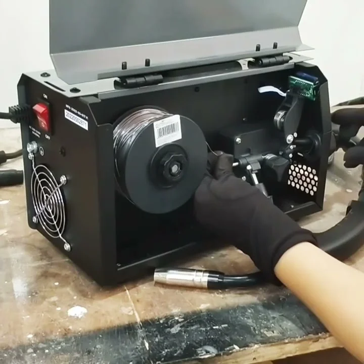
- Wire type: Identify solid MIG wire, gasless flux-cored wire, or gas-shielded flux-cored wire.
- Diameter: Match the spool diameter to the machine’s capacity and the wire size to the feed components.
- Polarity: Verify the terminal arrangement required by the wire manufacturer and machine instructions.
- Consumables: Have the correct contact tip and drive-roll groove available before loading.
Solid wire versus flux-cored wire
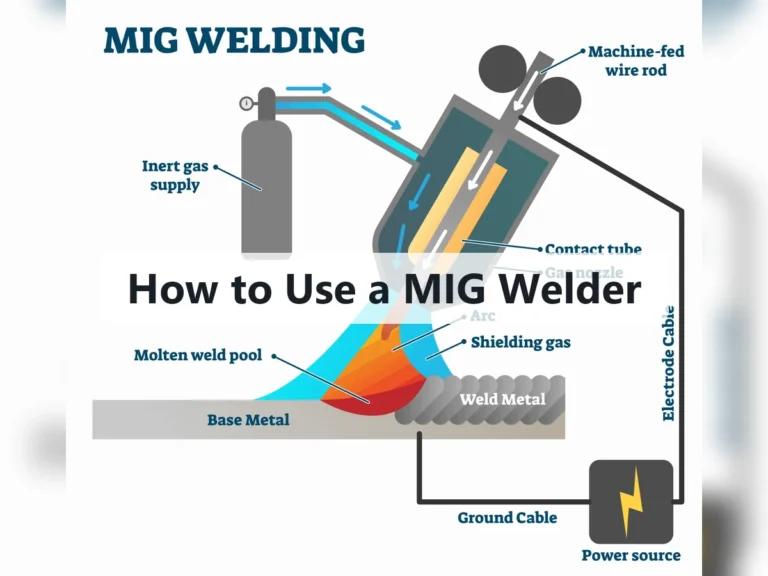
Solid wire normally operates with shielding gas supplied through the gun while self-shielded flux-cored wire generally does not use external gas The distinction changes more than the gas.
For solid wire a smooth V-groove drive roll usually grips the wire without marking it excessively Flux-cored wire is softer and hollow so a knurled or otherwise suitable.
Tools and parts that make loading easier
Keep the correct contact tip, nozzle, wire cutters, and a clean rag nearby. A small brush can remove dust from the drive area, while the welder’s manual can identify the brake adjustment, release lever, polarity terminals, and threading diagram.
Do not use pliers to crush or sharply bend the wire near the spool. A clean cut with wire cutters gives the leading end a manageable shape and reduces the chance that a rough end will catch inside the liner.
Prepare the Welder and Spool Safely
Start with the power switch off and disconnect the welder from its power source when the machine design permits Remove the gun from the work area keep the.
Open the side cover and inspect the spool compartment Look for loose wire metal dust a damaged spindle or a brake that is too loose The spool should.
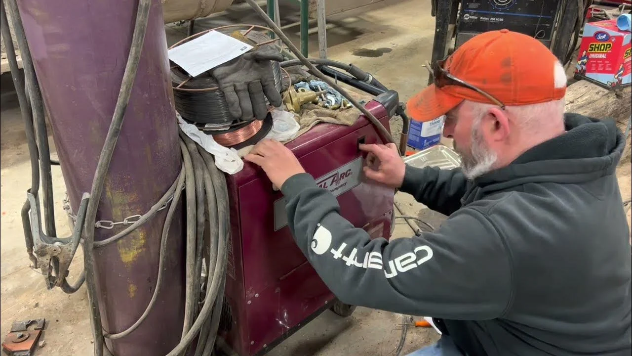
- Stop accidental feeding: Switch off and unplug the welder before installing the spool or working around the drive rolls.
- Protect your hands: The cut end of welding wire is sharp; wear suitable gloves and keep your face away from the gun tip.
- Secure the spool: Keep a hand on the wire whenever the retaining nut is released so the coil cannot spring loose.
- Control the work area: Remove flammable materials and use ventilation appropriate for welding fumes once welding begins.
Remove the old spool without losing control
Hold the wire near the spool with one hand before releasing the retaining nut or spool lock. If the free end slips into the coil, the spool can unwind and create overlapping loops that later snag in the drive system.
Cut the old wire close to the spool and secure its end in one of the spool’s retaining holes, if provided. Remove the spool and check that the spindle adapter, friction surfaces, and retaining hardware are clean and correctly positioned for the replacement spool.
Set the spool brake correctly
The brake prevents the spool from continuing to spin after the drive motor stops. It should be tight enough to stop overrun but loose enough that the drive motor does not struggle to pull wire.
A brake that is too loose allows a loop to spill off the spool A brake that is too tight can cause erratic feeding increase motor load and.
Thread the Wire Through the Drive System and Gun
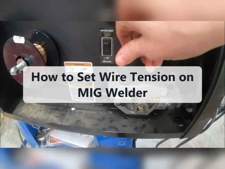
Place the spool on the spindle with the wire leaving in the correct direction. Install the retaining hardware and verify that the spool spins freely but does not wobble. Keep the wire end under control while you guide it toward the inlet guide.
Release the drive-roll pressure arm or tension lever Straighten the first several inches of wire cut off any bent section and feed the end through the inlet guide.
- Release pressure: Open the pressure arm before inserting wire so the leading end does not scrape across a clamped roll.
- Follow the path: Guide the wire through each inlet and outlet guide, not around the drive roll or beside the groove.
- Keep it straight: Straighten the gun cable and avoid tight loops while the wire travels through the liner.
- Secure the end: Hold the spool or use its retaining hole whenever you pause during installation.
- Cut the wire cleanly and remove a hooked or flattened end.
- Insert the wire into the inlet guide until it reaches the drive-roll groove.
- Continue through the outlet guide and into the gun liner.
- Close the pressure arm without fully tightening the tension adjustment.
- Cut or remove the protruding wire only after it is safely controlled.
Feed wire through the liner
With the machine still off push the wire gently into the liner rather than forcing it You should feel steady resistance but a sudden stop usually indicates a.
If the wire stops before reaching the gun open the drive arm and inspect the inlet and outlet guides Never solve a blockage by applying heavy pressure with the drive.
Install the contact tip and nozzle
Remove the nozzle if access is limited, then confirm that the contact tip matches the wire diameter. Thread the tip into the gun diffusor by hand first to avoid cross-threading, and tighten it appropriately with the supplied wrench rather than overtightening it. This distinction matters when answering “how to install wire in mig welder”.
The wire should pass through the tip s bore without binding If the tip is plugged with spatter worn oval or incorrectly sized replace it Reinstall the nozzle.
Use the trigger to advance the wire
After the wire is correctly routed, reconnect power according to the machine’s instructions and point the gun away from yourself, other people, and anything that could be damaged. Keep your hands clear of the contact tip and use the trigger briefly to advance the wire.
Many machines feed wire when the trigger is pressed even if the arc is not established so the wire can emerge unexpectedly Stop when a short length extends.
Keep the gun cable in a gentle, natural curve during the first feed test. If the wire advances when the cable is straight but stalls when it bends, suspect liner friction or a damaged liner rather than immediately increasing drive-roll pressure.
Adjust Drive-Roll Pressure and Wire Tension
Drive-roll tension is one of the most misunderstood parts of wire installation. The roll must grip the wire firmly enough to push it through the liner, but excessive pressure can flatten solid wire, deform flux-cored wire, and make a restriction harder to diagnose.
Begin with the tension setting low then increase it in small steps while using the trigger The goal is smooth feeding without slipping grinding or visibly crushing the.
- Too little: The roll slips, the motor turns without advancing wire, or the arc repeatedly loses contact.
- Too much: The wire becomes flattened or marked, the liner fills with filings, or a hidden obstruction remains masked.
- Correct setting: Wire advances steadily and the roll grips without severe indentation.
A simple slip test
Some welders allow a basic test in which the gun is held straight and the wire is briefly fed against a safe nonconductive surface or with the contact.
Use caution because test methods differ and the energized wire can still cause injury or an unintended arc If your manual does not describe a test use the.
Why more tension is not always the answer
When wire stops feeding, increasing tension may temporarily force it through a dirty liner or poorly aligned guide. The apparent improvement is misleading: the extra pressure can shave metal from solid wire or collapse flux-cored wire, sending debris into the liner and contact tip.
Check the spool brake, guide alignment, cable position, liner condition, and tip before making a major tension change. A properly installed system normally needs moderate pressure, not the maximum setting.
Set the Gun, Polarity, and Welding Controls
Once the wire reaches the gun consistently configure the machine for the wire and welding process Use the wire chart as a starting point for voltage and wire.
Polarity is especially important. Solid wire with conventional shielding gas commonly uses electrode-positive direct current, while many self-shielded flux-cored wires use electrode-negative direct current. These are general process patterns, not substitutes for the wire manufacturer’s instructions.
- Wire feed speed: Set it for the wire diameter and material thickness shown on the machine chart.
- Voltage: Adjust it with wire speed to obtain a stable arc rather than changing one control randomly.
- Polarity: Match the terminal arrangement to the specific solid or flux-cored wire.
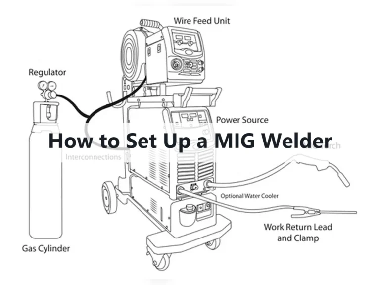
- Gas delivery: For gas-shielded wire, confirm the regulator, hose, flow setting, and nozzle path are unobstructed.
Trim stick-out after feeding
Trim the wire so the extension beyond the contact tip suits the process and machine guidance. Excessive stick-out can make the arc unstable, while very short stick-out increases the chance that the tip overheats or contacts the molten puddle.
The correct distance also depends on whether you are using solid wire or flux-cored wire, the transfer mode, and the welding position. Use the machine’s chart and the wire instructions rather than treating one measurement as universal.
Check the first weld on scrap
Before welding the actual workpiece clean a test area and make a short bead Listen for a consistent arc observe whether the wire burns back toward the tip.
Change one control at a time If the wire speed is too high for the selected voltage the wire may stub into the work If voltage is too.
Common Installation Mistakes and Feeding Failures
Most feeding problems occur at interfaces where the spool meets the brake where the wire enters the guide where the drive roll grips it or where the liner. Keep these limitations in mind when considering “how to install wire in mig welder”.
When diagnosing a problem, note when it occurs. A failure at the spool points toward brake tension or tangled wire; a failure only with the gun bent points toward liner friction; and a failure at the tip points toward contact-tip size, spatter, or burnback.
- Wrong groove: Using a roll that does not suit the wire type prevents consistent grip.
- Wrong tip: A mismatched or blocked contact tip restricts the final part of the path.
- Overtightened roll: Excessive pressure deforms wire instead of fixing the underlying restriction.
- Loose spool brake: Spool overrun creates loops that can catch and form a bird’s nest.
Bird’s nest at the drive rolls
A bird s nest is a tangled mass of wire around the drive-roll area Turn off and disconnect the welder release the pressure arm and cut the wire.
After clearing it, inspect the inlet guide, roll alignment, and spool brake. Bird’s nests commonly result from insufficient drive pressure, a misaligned guide, a wire end that missed the liner, or a spool that continued spinning after the motor stopped.
Wire slips or feeds intermittently
Clean the drive-roll groove and verify that the selected groove matches the wire diameter. Replace a worn roll if its edges are polished, damaged, or no longer grip the wire evenly.
Then inspect the liner and contact tip. Dirt, rust, a kinked cable, or a tip that is too tight can create enough resistance to make feeding intermittent. Straighten the cable and test again before increasing pressure.
Wire burns back to the tip
Burnback occurs when the wire melts back and fuses to the contact tip. It can be caused by wire feed interruption, incorrect settings, excessive stick-out changes, or a tip that is worn or contaminated.
Turn off the machine before removing the fused wire. Replace the tip if it is damaged, trim the wire cleanly, and check that the drive system feeds continuously. If the problem returns, review the wire speed and voltage relationship rather than simply installing another tip.
Wire will not pass through the liner
Withdraw the wire and inspect its leading end. A bent, flattened, or rough end can catch immediately at the liner entrance. Cut it back to clean, straight wire and try again with the cable gently extended.
If the obstruction remains the liner may be contaminated kinked incorrectly seated or worn Some liners can be removed and cleaned according to the gun manufacturer s procedure.
Differences Between MIG and Flux-Cored Wire Installation
The mechanical loading sequence is broadly similar for solid and flux-cored wire but the consumables and operating setup are not interchangeable in every case A flux-cored wire s.
Gas-shielded flux-cored wire uses external shielding gas, whereas self-shielded flux-cored wire is designed to create its own shielding. Follow the spool label and machine instructions for polarity, drive-roll selection, nozzle use, and settings.
| Feature | Solid wire | Flux-cored wire |
|---|---|---|
| Wire construction | Solid metal wire | Tubular wire containing flux |
| Typical shielding | External shielding gas | Self-shielded or external gas, depending on wire |
| Drive-roll consideration | Often a smooth V-groove | Often a knurled or specified groove |
| Polarity | Commonly electrode positive, but verify | Varies by wire; verify the spool instructions |
| Handling concern | Can kink or bird’s-nest when unsupported | Can crush under excessive roll pressure |
- Do not copy settings: The same diameter does not mean the same polarity, gas requirement, or drive-roll pressure.
- Protect the wire: Store opened spools dry and clean; contamination affects feeding and weld quality.
- Follow the label: The wire classification and manufacturer’s instructions control when general MIG habits conflict.
Maintenance After Installing Welding Wire
Good loading is easier when the feed system is maintained. Dust, grinding debris, rust, and wire shavings can collect around the rolls and guides. Clean the accessible areas during spool changes, but avoid blowing debris deeper into the liner or machine with uncontrolled compressed air.
Keep the gun cable protected from crushing and repeated sharp bends. Store the spool in a dry location and cover it when it is not in use, especially if the wire is susceptible to moisture or surface oxidation.
- Every spool change: Inspect the wire end, spool brake, drive-roll groove, and guide alignment.
- When feeding changes: Check for filings, worn rolls, liner friction, and contact-tip wear.
- During storage: Protect opened wire from moisture, dirt, and accidental unwinding.
- Before welding: Confirm the nozzle, tip, polarity, gas path, and machine settings.
When to replace the liner
Consider liner replacement when a clean, correctly sized wire still feeds poorly, especially if feeding changes as the gun cable moves. A liner can wear internally, develop a kink, or become packed with metal dust.
Use the liner size specified for the wire range and gun model A liner that is too large may allow the wire to wander while one that is.
FAQ: Installing Wire in a MIG Welder
Which way should the wire spool face?
Install the spool so the wire leaves from the direction shown by the welder’s threading diagram, normally from the lower side toward the inlet guide. The spool should unwind without crossing over itself, and the retaining hardware should hold it firmly without preventing smooth rotation.
Should the wire go over or under the spool?
In most MIG machines, the wire leaves from the bottom of the spool as it travels toward the drive rolls. The exact route depends on the machine design, so follow the diagram inside the side cover rather than relying on a generic assumption.
Why does my MIG wire keep tangling near the drive rolls?
The usual causes are insufficient drive-roll pressure, a loose spool brake, a misaligned inlet guide, or wire that was not inserted into the liner. Turn off the machine, clear the tangle, and correct the wire path before trying to feed again.
How tight should MIG drive-roll tension be?
Set it only tight enough to feed wire steadily without slipping. Excessive tension can flatten solid wire, crush flux-cored wire, create shavings, and conceal a dirty liner or blocked contact tip.
Can I install a different wire diameter without changing the contact tip?
No. The contact tip should match the wire diameter, and the drive roll and liner must also support that size. A mismatch can cause binding, erratic electrical contact, poor arc stability, and accelerated wear.
Why does the wire stop when I bend the gun cable?
A sharp bend increases friction and may expose a damaged or contaminated liner. Straighten the cable, check the wire path, and inspect the liner and contact tip before increasing drive-roll pressure.
Do solid wire and flux-cored wire load the same way?
The basic path is similar, but they may require different drive rolls, polarity, shielding, nozzle practices, and settings. Always confirm the spool instructions and machine chart for the specific wire.
Conclusion
Installing wire correctly involves a controlled path from the spool through the guides drive rolls liner and contact tip Match every component to the wire diameter and type.
If feeding remains inconsistent stop and inspect the path instead of forcing the wire or tightening the roll to its limit With the machine powered down during setup.
Before your next weld, compare the spool label, drive-roll groove, contact-tip marking, polarity, and machine chart, then perform a short feed test on scrap.
The answer to “how to install wire in mig welder” should be applied with these conditions and limitations in mind.