How to MIG Weld Mild Steel: Practical Steps and Helpful Tips
To MIG weld mild steel, clean and fit the joint, use ER70S-6 wire with shielding gas, set the machine correctly, and weld with a steady travel angle.
MIG welding mild steel is approachable because the process is fast, versatile, and easier to control than many manual arc-welding methods. The quality of the finished joint, however, depends less on simply pulling the trigger than on preparing the steel, matching the wire and gas, and controlling heat.
For most clean ordinary steel a solid wire such as ER70S-6 paired with an argon-and-carbon-dioxide mix provides a smooth arc and manageable spatter Flux-cored wire can be useful. This guide examines “how to mig weld mild steel” and explains the details that matter in practice.
This guide explains how to mig weld mild steel in a practical sequence from safety and joint preparation through machine setup tack welding travel technique and inspection It.
- ✓Clean steel, correct polarity, suitable shielding gas, and a stable work clamp are the foundation of a sound MIG weld.
- ✓Use machine charts as a starting point, then tune voltage and wire speed with a test weld on matching scrap.
- ✓Keep a short, consistent arc, maintain the correct gun angle, and move quickly enough to control heat without sacrificing fusion.
- ✓Spatter, porosity, burn-through, and poor penetration usually point to a specific setup, preparation, or technique problem.
How to MIG Weld Mild Steel
Mild steel generally refers to low-carbon steel that is easy to form and weld compared with higher-carbon or alloy steels It is common in brackets frames gates automotive.
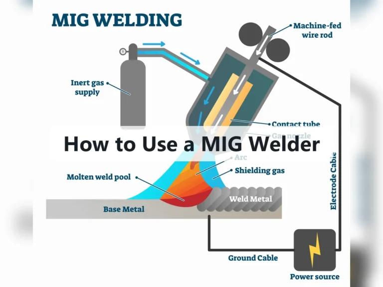
For indoor work on clean or moderately clean steel a conventional MIG setup uses a constant-voltage power source a solid steel wire and an external shielding gas The.
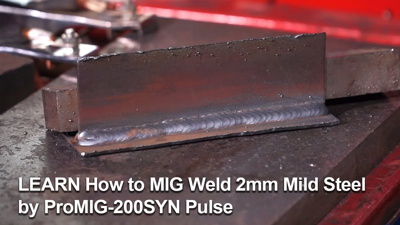
- Wire: ER70S-6 solid wire is a practical general-purpose choice because its deoxidizers tolerate small amounts of mill scale better than some other solid wires.
- Gas: A common mixed gas is approximately 75 percent argon and 25 percent carbon dioxide; higher carbon dioxide content can increase penetration and spatter.
- Polarity: Solid wire with shielding gas normally runs electrode positive, often marked DCEP or reverse polarity.
- Work area: Keep the weld zone protected from drafts that can blow shielding gas away from the arc.
Solid wire or flux-cored wire?
Solid MIG wire usually produces a clean-looking weld with minimal slag making it convenient for indoor fabrication and visible joints It requires a gas cylinder regulator hose and.
Self-shielded flux-cored wire carries its own shielding ingredients inside the tubular wire It is better suited to outdoor repairs windy conditions and some heavier work but it creates.
Do not assume every flux-cored wire is interchangeable. Gas-shielded flux-cored wire has different requirements from self-shielded wire, and the package instructions control polarity, gas, and operating range. When in doubt, verify the wire classification and machine settings before striking an arc.
Choose wire diameter by the work
Common solid-wire diameters include 0 023 0 030 and 0 035 inch Smaller wire is easier to control on thin sheet and generally needs less current Larger wire.
A 0.030-inch wire is a flexible general-purpose option for many home and light-fabrication jobs. It is not a universal answer: use the machine’s chart, the wire manufacturer’s range, and the material thickness as the final guides.
Prepare the Steel, Joint, and Welding Area
Preparation determines whether the arc can melt clean base metal and whether the weld pool can flow into the joint. Paint, rust, oil, galvanized coatings, heavy mill scale, and moisture can create porosity or inclusions. They can also produce hazardous fumes, especially when coatings are heated.
Remove contaminants from both sides of the joint and from the area where the work clamp will attach A wire wheel flap disc scraper or suitable solvent may.
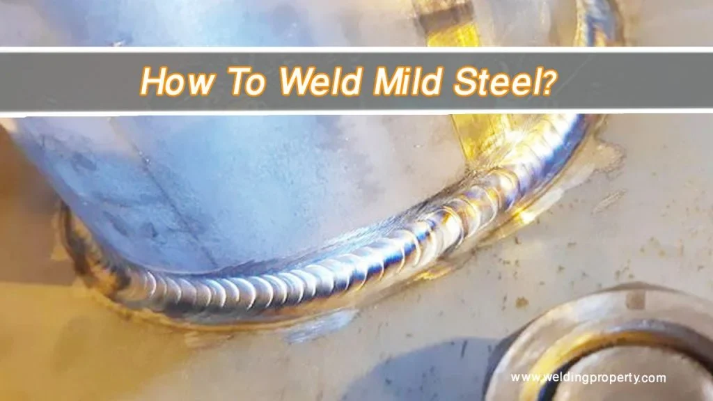
- Clean the joint: Grind or brush to bright metal where the arc and weld pool will travel.
- Control the fit-up: Keep gaps consistent and avoid forcing badly misaligned pieces together.
- Expose clean clamp contact: Attach the work lead to bare, sound metal close enough to the joint for a stable circuit.
- Plan access: Make sure the gun can reach the joint at a comfortable angle without stretching or twisting your body.
Joint fit-up and edge preparation
For thin sheet a tight butt joint can reduce the chance of falling through the gap although a small consistent root opening may be appropriate on thicker material.
Lap joints and outside corners often need less preparation than thick butt joints Even so excessive overlap can trap contaminants and leave an unwelded edge Clamp the pieces.
Tack weld before making the final pass
Use small, evenly spaced tack welds to hold the parts in alignment. Check squareness and dimensions after tacking because heat can pull the joint out of position. On long seams, alternate tack locations and weld in short sections when practical to reduce distortion.
Make sure each tack is fused to both pieces A tall blob sitting on top of one edge can break loose or create a lack-of-fusion area beneath the.
Safety before the arc starts
Wear a properly rated welding helmet flame-resistant clothing leather gloves sturdy closed footwear and suitable eye protection for grinding Welding produces ultraviolet radiation hot metal sparks fumes and.
Use local exhaust or respiratory protection when the material, coating, or workspace creates a fume risk. Do not weld galvanized, painted, or unknown steel casually; coatings can release dangerous substances. Inspect the gun, liner, cable, regulator, and ground lead, and keep the gas cylinder upright and secured.
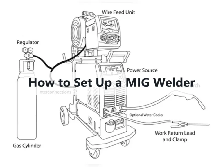
Set Up the MIG Welder Correctly
Before adjusting the machine confirm the wire type diameter polarity and gas requirement Install the spool so the wire feeds from the bottom or top according to the. This distinction matters when answering “how to mig weld mild steel”.
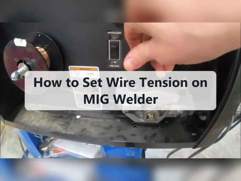
Thread the wire through the inlet guide, drive rolls, outlet guide, liner, and contact tip. Keep the gun cable as straight as practical while feeding. If the wire hesitates, slips, or burns back into the tip, stop and find the cause instead of repeatedly increasing drive-roll pressure.

- Polarity: Match the terminal arrangement to the wire manufacturer’s instructions; solid gas-shielded wire is commonly electrode positive.
- Gas flow: Set enough flow for reliable coverage without creating turbulence that draws air into the weld pool.
- Contact tip: Use a tip matched to the wire diameter and replace it if the opening is worn or irregular.
- Stickout: Begin with a short, consistent distance from the contact tip to the work, following the wire instructions rather than letting the distance grow uncontrolled.
Voltage and wire speed work together
On a typical constant-voltage MIG machine voltage strongly affects arc length and bead profile while wire speed largely controls amperage and deposition rate These controls interact Increasing wire.
Use the welder’s chart as the starting point for material thickness, wire diameter, and gas. The chart cannot account for every joint position, fit-up gap, stickout, machine calibration, or operator preference, so always confirm the setting with a test bead.
Test on matching scrap
Use a piece of steel with the same approximate thickness and surface condition as the workpiece Make a short bead listen to the arc and examine the bead.
If the wire repeatedly stubs into the plate the wire speed may be too high for the voltage the stickout may be too short or the workpiece may.
Gas flow and wind protection
Set gas flow according to the regulator scale and the wire or machine guidance. More flow is not automatically better. Excessive flow can create turbulence at the nozzle, while low flow or a leaking connection can allow air into the shielding envelope.
Check the cylinder valve regulator connection hose fittings and gun diffuser for leaks Avoid welding where fans open doors or outdoor wind can disturb the gas If outdoor.
Use a Controlled MIG Welding Technique
Hold the gun so the nozzle stays clear of the joint and the contact tip maintains a consistent relationship to the work A slight work angle and a.
For many mild-steel joints a small forehand or push angle improves visibility and can produce a flatter bead with less penetration A slight backhand or pull angle may.
- Arc length: Keep the distance consistent; a long arc increases spatter and weakens shielding, while a short arc can cause sticking.
- Travel speed: Move fast enough to avoid excessive heat, but slow enough for the pool to wet both sides of the joint.
- Gun angle: Maintain a modest angle rather than pointing sharply into one edge.
- Bead placement: Watch the leading edge of the puddle and ensure it reaches both joint members.
Stringer beads versus weaving
A narrow stringer bead is often the best starting technique for mild steel It limits heat input is easier to inspect and reduces the chance of trapping gas or slag For a wider joint use multiple stringer beads rather.
A small weave may help bridge a gap or distribute metal across a fillet, but wide weaving adds heat and can leave the edges cold if the pause is poorly controlled. If you weave, pause briefly at each side to establish tie-in, then cross the center without lingering.
Controlling thin sheet and tubing
Thin steel is often more difficult than thicker plate because it reaches melting temperature quickly. Use the lowest practical heat input that still creates fusion, keep the travel moving, and consider short stitch welds instead of one continuous bead. Welding from alternating sides can reduce warping.
When a hole begins to form stop advancing the puddle and let the area cool You can sometimes bridge the opening with brief trigger pulses around the edge.
Welding in position
Flat-position welding is generally easiest because gravity helps keep the pool in place. Horizontal fillets require more control, while vertical and overhead work usually need lower heat input, a smaller puddle, and a deliberate progression.
For vertical-up work short arc transfer and a controlled side-to-side motion may help support the molten metal but the exact method depends on the machine wire and thickness. Keep these limitations in mind when considering “how to mig weld mild steel”.
Inspect the Weld and Recognize Defects
A good-looking bead is not automatically a strong weld Inspect the start and finish the tie-in along both edges the consistency of the profile and any visible cracks.
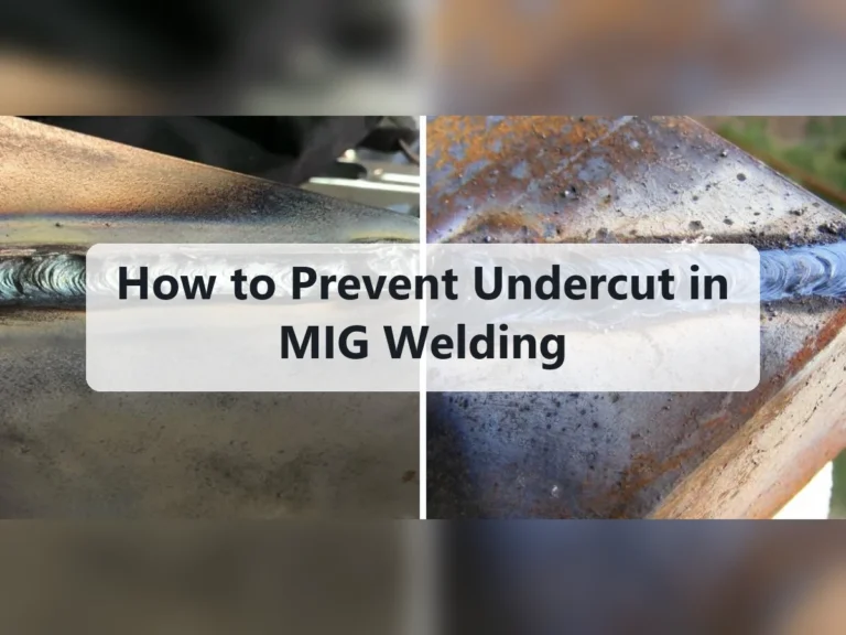
Look for a bead that blends smoothly into the base metal without sharp undercut excessive convexity overlap crater cracks or visible porosity Remove spatter and slag before judging.
- Porosity: Pinholes or bubbles can indicate contamination, gas loss, drafts, excessive stickout, or a blocked nozzle.
- Undercut: A groove beside the bead often comes from excessive voltage, too much travel speed, or dwelling incorrectly at the edge.
- Lack of fusion: Cold-looking edges or an unwelded root may result from low heat, fast travel, poor fit-up, or an incorrect angle.
- Excessive spatter: An unstable voltage-to-wire-speed relationship, long arc, dirty steel, or poor gas coverage may be responsible.
What the bead profile can tell you
A narrow high bead may indicate insufficient voltage slow wire speed relative to voltage a short travel distance or inadequate wetting A very wide flat bead can indicate.
A crater at the end of the weld can crack as it cools Fill the crater by briefly reducing travel or using the machine s crater-fill function if.
Clean between passes
Solid-wire MIG does not normally leave a slag layer, but spatter, oxides, and silicon-rich residue can still interfere with subsequent passes. Brush or grind as needed, especially at starts, stops, and joint edges. Flux-cored welds require thorough slag removal before another pass.
Do not hide defects under another layer. If a pass contains a crack, deep undercut, trapped slag, or obvious lack of fusion, remove the affected area and correct the cause before proceeding.
Troubleshoot Common MIG Problems
When a weld goes wrong, change one factor at a time and make another short test bead. Randomly adjusting voltage, wire speed, gas, stickout, and travel speed together makes it difficult to identify the actual cause.
Start with simple checks: clean the joint, confirm the work clamp, inspect the nozzle, verify polarity, check gas flow, and make sure the wire is feeding smoothly. Mechanical problems in the liner, drive rolls, contact tip, or gun cable can imitate incorrect settings.
- Chasing the arc: Moving the gun too far from the work lengthens the arc and increases spatter.
- Overusing heat: A slow travel speed may create a wide bead while distorting or weakening thin material.
- Ignoring the ground: A loose or dirty work connection can cause an unstable arc and inconsistent penetration.
- Welding through scale: Surface contamination can make the machine settings appear wrong when preparation is the real problem.
| Symptom | Likely causes | First checks |
|---|---|---|
| Wire stubs into the plate | Wire speed too high, voltage too low, poor feed, short circuit at the tip | Check settings, tip condition, liner, and drive-roll tension |
| Large amounts of spatter | Incorrect voltage and wire-speed balance, long stickout, dirty steel, poor gas coverage | Clean metal, shorten stickout, verify gas and tune the arc |
| Porous weld | Gas leak, wind, blocked nozzle, contamination, insufficient flow | Inspect hose and nozzle, shield the area, clean the joint |
| Burn-through | Too much heat, slow travel, excessive gap, thin material | Lower heat input, use short stitches, improve fit-up |
| Poor penetration | Low heat, fast travel, incorrect angle, tight contamination or poor joint access | Clean, slow slightly, adjust settings, and check joint preparation |
When wire feeding becomes unreliable
Bird-nesting usually occurs when wire cannot move smoothly through the gun. Causes include excessive drive-roll tension, a blocked liner, a worn contact tip, a kinked cable, or an incorrect guide setup. Cut the wire, remove the tangled section, and inspect the complete feed path before restarting.
Keep the spool brake tight enough to stop overrun but loose enough for smooth feeding. Replace liners and tips when wear or contamination causes drag. Do not use pliers to force wire through a damaged path; that can create a sharper kink and make the problem worse.
Know the Limits of MIG Welding Mild Steel
MIG is productive and convenient but it is not automatically suitable for every mild-steel repair Very thin sheet may demand pulse capability short stitch welding backing or a.
Steel identification also matters A piece that looks like ordinary mild steel may be galvanized painted high-strength weathering or alloyed Unknown material can respond differently to heat and.
- Choose solid-wire MIG: Indoor fabrication on clean steel where speed, low cleanup, and a visible bead are priorities.
- Choose self-shielded flux core: Outdoor work or locations where wind makes external shielding unreliable, provided polarity and wire requirements are followed.
- Consider TIG: Thin, highly visible, or precision joints where maximum control and low spatter matter more than deposition speed.
- Consider stick welding: Outdoor or heavy-steel work where portability and tolerance of less-than-perfect conditions outweigh cleanup.
Heat distortion and residual stress
Every weld contracts as it cools, and that contraction can pull a frame, panel, or tube out of alignment. Reduce distortion by improving fit-up, using balanced weld sequences, making shorter passes, clamping appropriately, and avoiding unnecessary oversize welds.
Do not quench a hot weld with water unless a qualified procedure specifically calls for it. Rapid, uncontrolled cooling can affect the steel and may increase stress. Let ordinary mild-steel work cool naturally while keeping people away from hot metal.
FAQ: How to MIG Weld Mild Steel
What gas is best for MIG welding mild steel?
A common general-purpose choice is an argon-and-carbon-dioxide blend, often around 75 percent argon and 25 percent carbon dioxide. It usually provides a smoother arc and less spatter than straight carbon dioxide, although pure carbon dioxide can offer deeper penetration at the cost of a rougher arc and more spatter.
What wire should I use for mild steel MIG welding?
ER70S-6 solid wire is a common choice for general mild-steel work because its deoxidizers help handle small amounts of surface scale. Choose the diameter based on material thickness, machine capacity, joint position, and the operating range printed on the wire and welder documentation.
Should MIG wire for mild steel be positive or negative?
Solid wire used with external shielding gas is commonly run electrode positive, also called DCEP or reverse polarity. Self-shielded flux-cored wire often uses electrode negative, but the correct polarity is determined by the specific wire classification and manufacturer instructions.
How far should the MIG gun be from mild steel?
Keep a short, steady stickout appropriate to the wire and transfer mode, commonly roughly 3/8 to 1/2 inch for many short-circuit setups. The exact distance varies, so follow the wire guidance and focus on consistency rather than measuring every moment.
Can I MIG weld rusty mild steel?
Light surface scale may be tolerated by some deoxidized wires, but rust, oil, paint, and heavy mill scale should be removed from the joint. Welding over contamination increases the risk of porosity, slag-like inclusions, poor fusion, and excessive spatter.
Why does my MIG weld have holes?
Holes or pinholes usually indicate porosity. Check for drafts, empty or poorly connected gas supply, leaks, a blocked nozzle, excessive stickout, contaminated steel, or gas flow that is too low or turbulent. Clean the joint and make a short test bead after correcting one suspected cause.
How do I avoid burning through thin mild steel?
Use a suitable small wire, the lowest practical heat that still produces fusion, a short controlled arc, and steady movement. Tack and stitch-weld instead of making a long continuous pass, reduce excessive gaps, and allow the panel to cool between sections.
Conclusion
Reliable MIG welding of mild steel comes from a repeatable sequence identify the material clean and fit the joint select compatible wire and gas verify polarity tune the.
Protect yourself from arc radiation, fumes, hot metal, fire, and electrical hazards, and treat unknown coatings or critical structures seriously. For ordinary fabrication, careful preparation and small controlled adjustments will usually improve the weld faster than simply turning up the power.
Clean and tack a piece of matching scrap, set the machine from its chart, and make a short test bead before welding the actual mild-steel joint.
The answer to “how to mig weld mild steel” should be applied with these conditions and limitations in mind.