How Does Wire Speed Affect MIG Welding: Causes, Signs, and Fixes
Wire speed primarily controls MIG welding amperage and deposition rate: increasing it usually makes the weld hotter and larger, while decreasing it makes the arc cooler and smaller.
For anyone asking how does wire speed affect mig welding the key is understanding that wire speed is not an isolated dial In a constant-voltage MIG system the.
That relationship explains why a small adjustment can change arc sound bead profile spatter penetration and even whether the wire burns back into the contact tip However many.
Acting early matters when a bead is clearly cold excessively convex unstable or producing dangerous lack of fusion It is unnecessary when the apparent defect comes from fit-up.
- ✓Higher wire speed normally increases amperage, deposition rate, weld size, and heat input.
- ✓Lower wire speed normally reduces amperage and deposition, but too little can cause burnback and poor fusion.
- ✓Wire speed and voltage must be balanced; changing one often requires a related adjustment to the other.
- ✓Stickout, travel speed, shielding gas, polarity, material thickness, and joint fit-up can imitate a wire-speed problem.
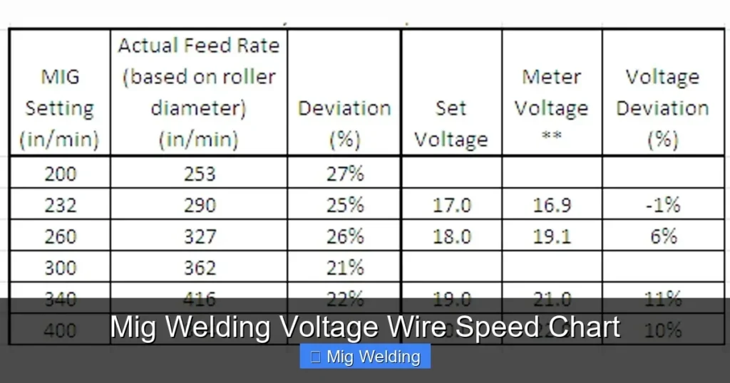
- ✓Use the machine’s wire-speed units and welding chart as a starting point, then fine-tune on scrap of the same material.
How Does Wire Speed Affect MIG Welding?
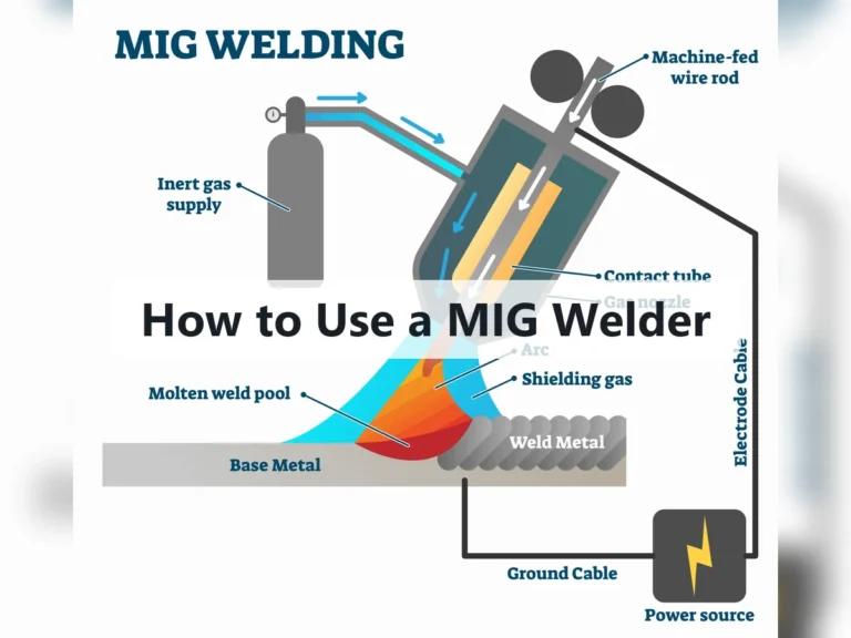
Wire speed determines how quickly the electrode travels from the spool through the drive rolls and contact tip and into the arc It is commonly expressed in inches.
On a typical constant-voltage MIG or flux-cored setup, this creates a useful practical rule: wire speed is the primary amperage control. The exact amperage depends on wire diameter, material, polarity, stickout, shielding gas, and transfer mode, so a wire-speed number cannot be compared meaningfully across every machine or process.
- Higher speed: Usually increases amperage, deposition rate, bead volume, and penetration potential.
- Lower speed: Usually reduces amperage and deposited metal, producing a smaller and cooler weld.
- Voltage relationship: Wire speed controls how much wire enters the arc, while voltage strongly influences arc length and bead width.
- Process limitation: The machine’s chart and operating range still govern what settings are practical.
Why the wire-speed-to-amperage relationship exists
Every inch of electrode wire must be melted before it becomes part of the weld If the feeder supplies more wire each minute the arc must melt that.
This is why turning up wire speed often makes the arc sound more forceful and the bead wider or more substantial It also explains why wire speed can.
Wire speed is not the same as travel speed
Wire speed describes electrode delivery. Travel speed describes how quickly the torch moves along the joint. Increasing wire speed while holding travel speed constant usually deposits more metal in the same area.
Increasing travel speed while holding wire speed constant spreads less heat and metal over each inch of weld.
These controls can sometimes compensate for each other, but they are not interchangeable. A very fast travel speed can leave an undersized bead even with high wire speed, while an excessively slow travel speed can create a large, overheated bead at a moderate setting.
What Happens When Wire Speed Is Too High?
Wire speed is too high when the arc cannot melt and transfer the incoming electrode smoothly for the selected voltage wire diameter stickout and process The first signs.
In a short-circuit MIG setup, excessive wire speed often feels like the gun is trying to move backward. The wire repeatedly contacts the puddle, the arc extinguishes, and the machine produces popping or stubbing. This is commonly called wire stubbing or arc pushing.
- Harsh popping: The electrode is feeding faster than the selected voltage can melt it smoothly.
- Gun pushback: The wire physically drives into the puddle or workpiece.
- Excessive spatter: Droplet transfer becomes unstable instead of controlled.
- Overbuilt bead: Too much metal is deposited for the joint and travel speed.
Effects on bead shape and penetration
A high wire speed usually increases bead size and may increase penetration because amperage rises That does not guarantee better fusion If the wire pushes the torch away.
In a fillet weld, too much wire can cause a convex profile, excessive reinforcement, or overlap at the toes. On thin sheet metal, the additional heat and deposition can increase the risk of burn-through, especially when travel speed is slow or the joint has a gap.
How to correct an overly high setting
First, reduce wire speed in small increments while maintaining the torch position and travel technique. Listen for a smoother, more consistent arc rather than chasing a perfectly quiet sound; acceptable arc characteristics vary with wire type, transfer mode, and gas.
If lowering wire speed makes the arc too long, too soft, or inconsistent, the voltage may also need adjustment. Make one change at a time whenever possible, weld a short test section, and inspect the bead rather than relying only on sound.
What Happens When Wire Speed Is Too Low?
Wire speed is too low when the electrode does not provide enough current or deposition for the material joint and travel speed The arc may become weak the.
When wire speed is reduced substantially without matching the voltage the arc can become long and unstable The wire may melt before it reaches the puddle producing irregular.
- Confusing a cold weld with a low voltage: Low wire speed can reduce amperage, but voltage alone may be the real mismatch.
- Moving too fast: A small wire-speed setting becomes even less effective when travel speed is excessive.
- Trusting appearance only: A shiny bead can still have poor fusion or insufficient throat size.
- Ignoring joint fit-up: A wide gap may require a different technique or multiple passes, not simply more wire.
Burnback and contact-tip problems
Burnback occurs when the wire melts back toward the contact tip at the end of a weld or during an unstable arc Low wire speed is one possible.
If the wire repeatedly fuses to the tip, do not keep increasing wire speed blindly. Check that the contact tip matches the wire diameter, the drive rolls are correctly selected, the spool is not dragging, and the liner is clean and properly installed. This distinction matters when answering “how does wire speed affect mig welding”.
Cold lap and lack of fusion
A bead that sits on top of the base metal may indicate insufficient amperage from low wire speed but it can also result from a long arc incorrect.
For critical work, evaluate fusion according to the applicable welding procedure and inspection requirements rather than assuming a larger bead is safer. Adding metal on top of poorly fused metal does not repair the underlying defect.
How Voltage, Stickout, and Travel Speed Change the Result
Wire speed cannot be set correctly in isolation. MIG welding depends on a balanced combination of electrode feed, arc voltage, electrical stickout, travel speed, shielding, and joint geometry. A change in one variable can alter the way the others behave.
Voltage primarily affects arc length in a constant-voltage system Raising voltage tends to lengthen and broaden the arc while lowering it tends to shorten the arc Wire speed.
- Wire speed: Primarily changes amperage and deposition rate.
- Voltage: Primarily changes arc length, arc width, and the smoothness of transfer.
- Stickout: Changes electrode resistance and can reduce current when excessive.
- Travel speed: Changes how much heat and metal are placed along each inch of joint.
Why voltage and wire speed must be balanced
Consider a setting with high wire speed and low voltage The machine feeds substantial wire but the short arc may not melt it smoothly The result is often.
The correct balance depends on transfer mode Short-circuit transfer uses lower voltage and supports many common sheet-metal applications Spray transfer generally uses higher current and voltage ranges requires.
Electrical stickout matters
Electrical stickout is the distance from the contact tip to the point where the wire enters the arc. A longer stickout increases the length of wire being heated by resistance before it reaches the arc. This can reduce the current at the arc and alter deposition, penetration, and arc behavior.
For that reason, a welder who changes torch distance while trying to diagnose wire speed may be adjusting several variables at once. Hold a consistent stickout appropriate to the process and wire manufacturer’s guidance while testing settings.
Travel speed and heat distribution
Traveling slowly allows more heat and metal to accumulate in one location. With high wire speed, that can produce an oversized bead, excessive penetration, undercut at the edges, or burn-through. Traveling quickly reduces heat per unit length but may leave an undersized bead or incomplete fusion.
Use the weld’s required size and the material’s response as the decision point. A smooth sound does not compensate for a bead that is too small, too large, misplaced, or visibly discontinuous.
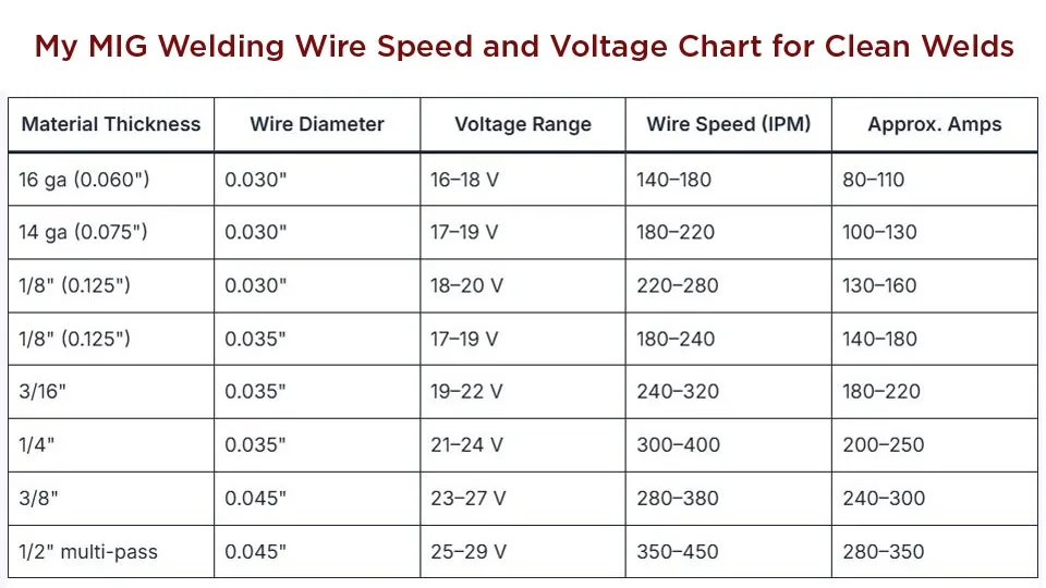
Choosing a Starting Wire-Speed Setting
The best starting point comes from the welding machine s chart the wire manufacturer s guidance or a qualified welding procedure for the specific wire diameter material shielding.
For solid MIG wire the chart normally pairs wire speed with voltage and identifies a material thickness range Flux-cored wire has its own operating characteristics and may require different polarity voltage stickout and gas practices A setting that works for solid ER70S-type wire.
- Wire diameter: Confirm the feeder, contact tip, drive rolls, and chart all match the selected wire.
- Base material: Match the starting range to the steel, stainless, aluminum, or other alloy being welded.
- Shielding: Use the gas type and flow range intended for the wire and transfer mode.
- Joint design: Account for thickness, gap, position, fillet size, and number of passes.
What to observe during a test weld
Make a short test weld on clean material similar in thickness and joint configuration to the actual work. Keep the torch angle, stickout, travel speed, and work angle consistent. Listen to the arc, watch the puddle, and inspect the bead profile after it cools.
A useful setting produces a stable arc, controlled puddle, adequate wetting at the toes, and a bead size appropriate to the joint. It should not require the operator to fight the gun, outrun the puddle, or compensate with an extreme torch angle.
| Observation | Likely direction to investigate | First practical check |
|---|---|---|
| Wire pushes into the puddle | Wire speed too high or voltage too low | Reduce wire speed slightly or verify the voltage match |
| Long, erratic arc with thin bead | Wire speed too low or voltage too high | Compare both controls with the machine chart |
| Large convex bead | Excessive deposition or slow travel | Check wire speed, travel speed, and torch angle |
| Burnback into tip | Low feed, high voltage, or feeding fault | Check contact tip, liner, drive rolls, and settings |
| Porosity | Shielding or contamination issue | Check gas flow, leaks, wind, nozzle, and cleaning |
Diagnosing a Wire-Speed Problem Before Adjusting the Dial
A structured diagnosis prevents unnecessary changes If the arc is unstable begin with the simplest physical causes spool drag wrong drive-roll tension a damaged liner a worn contact.
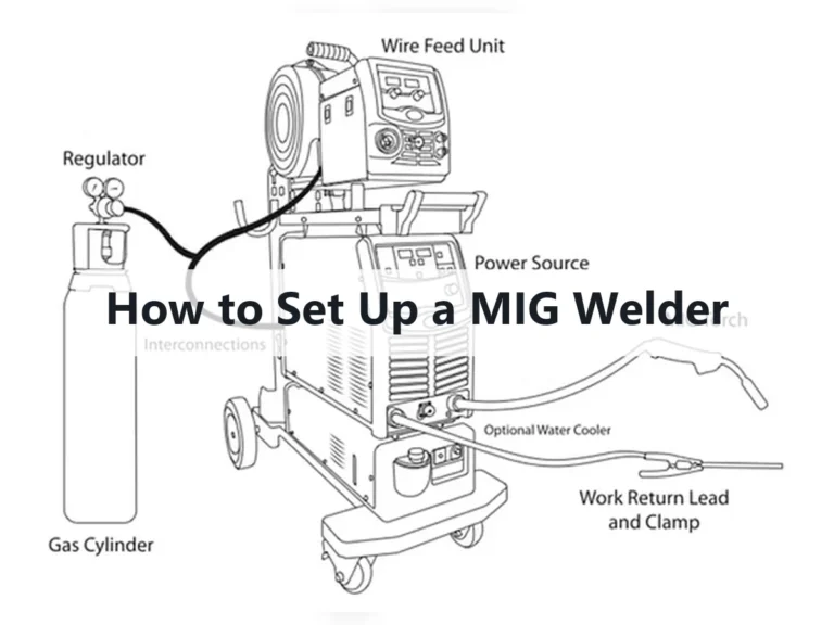
Then verify the consumable and machine setup. Confirm the wire diameter, drive-roll groove, contact-tip size, polarity, shielding gas, and gun connections. If the machine is set for a different process, adjusting wire speed alone may never produce a reliable arc.
Keep these limitations in mind when considering “how does wire speed affect mig welding”.
- Feeding path: The wire should move smoothly without bird-nesting, slipping, or excessive spool resistance.
- Contact tip: Replace a tip that is oversized, damaged, contaminated, or loose.
- Gas coverage: Check cylinder supply, regulator, hose connections, nozzle blockage, and drafts.
- Work connection: Clean and secure the work clamp and ensure the current has a sound return path.
Separate feeding faults from setting faults
Remove the gun from the work area and feed a short length of wire while observing the drive rolls and liner entrance The feeder should run steadily If.
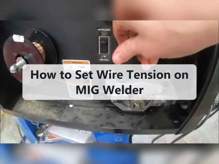
Do not use excessive drive-roll tension to overcome a blocked liner or tight contact tip. That can damage the wire and create inconsistent feeding. Correct the restriction, then set tension only high enough to feed reliably.
Check the joint and technique
Rust mill scale paint oil and moisture can create spatter porosity and poor wetting that resemble a setting problem Clean the joint and confirm the work angle directs.
Joint fit-up also matters. A large gap, an inconsistent root opening, or an oversized joint may require a different sequence or multiple passes. Raising wire speed to fill a difficult gap can overheat thin edges and leave an irregular weld.
Practical Adjustments for Common MIG Symptoms
Once the machine and joint are verified, adjust settings deliberately. Change wire speed in modest increments, then evaluate the arc and finished bead. If a wire-speed change creates a new arc-length problem, adjust voltage in the corresponding direction rather than continuing to move only one control.
For example if the wire is stubbing into the work a small reduction in wire speed may smooth the arc If the bead then becomes too narrow or.
- Change one variable: Avoid changing wire speed, voltage, travel speed, and stickout simultaneously.
- Use short tests: A few inches of weld is usually enough to reveal arc instability or poor bead shape.
- Inspect after cooling: Look for fusion, profile, undercut, porosity, cracks, and correct size.
- Record successful settings: Note wire, gas, polarity, thickness, position, and machine controls.
When the bead is too tall or narrow
A tall narrow bead may result from low voltage high wire speed fast travel or an incorrect torch angle First verify that the arc is aimed into the.
A narrow bead can also indicate insufficient side-to-side movement for a wide joint, although excessive weaving is not a substitute for proper settings. Keep any manipulation appropriate to the joint and qualified procedure.
When the bead is too wide or flat
A wide, flat bead may indicate excessive voltage, slow travel, long stickout changes, or a transfer mode that does not suit the application. High wire speed can add enough material to make the bead overly large, but reducing it may not correct an arc that is already too long.
Inspect the toes for undercut and the center for adequate reinforcement. The goal is controlled fusion and the required weld size, not the flattest appearance possible.
Special Considerations for Thin and Thick Material
Thin sheet requires careful control because a small increase in amperage can substantially change the puddle Lower wire speed short weld segments proper fit-up and appropriate travel speed.
Thicker material usually requires greater deposition and heat, often through higher wire speed, multiple passes, preheating where specified, or joint preparation. Increasing wire speed alone may produce a large surface bead without melting the joint deeply enough.
- Thin sheet: Prioritize controlled puddle size, short welds, good fit-up, and burn-through prevention.
- Thick plate: Prioritize joint preparation, adequate fusion, pass sequence, and the required weld size.
- Out-of-position work: Excessive wire speed can make the puddle difficult to control, especially overhead.
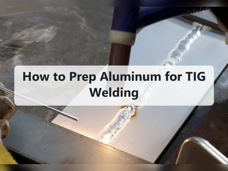
- Aluminum: Feeding friction, spool-gun setup, contact-tip fit, and push-pull equipment can be especially important.
Position changes the acceptable range
Flat-position welding generally allows a larger puddle and higher deposition than vertical or overhead work In vertical-up welding too much wire speed can cause the puddle to sag.
Always follow the qualified procedure when one applies. The machine’s general chart is a starting reference, not permission to ignore required process limits or inspection criteria.
FAQ: How Does Wire Speed Affect MIG Welding?
Does increasing wire speed increase MIG amperage?
Usually, yes. In a constant-voltage MIG system, increasing wire speed feeds more electrode into the arc, so the power source generally increases current to melt it. The actual amperage is influenced by wire diameter, stickout, polarity, transfer mode, and machine design.
Should I adjust wire speed or voltage first?
Start with the control that matches the symptom. If the bead is undersized and the arc is otherwise balanced, wire speed may need to increase. If the arc length is wrong or the wire is stubbing because voltage is mismatched, adjust voltage or the paired wire-speed setting.
What does wire speed do to penetration?
Higher wire speed usually increases amperage and can increase penetration potential. However, penetration also depends on travel speed, torch angle, stickout, voltage, joint geometry, polarity, and surface condition. More wire does not guarantee better fusion.
Why does my MIG wire keep burning back to the contact tip?
Possible causes include wire speed that is too low, voltage that is too high, excessive stickout changes, incorrect burnback timing, a worn or wrong-size contact tip, and inconsistent feeding. Inspect the feeding system and consumables before making a large setting adjustment.
Can too much wire speed cause spatter?
Yes. Excessive wire speed can make the wire push into the puddle, causing short-circuiting, popping, and spatter. Spatter can also result from incorrect voltage, poor gas coverage, contamination, wrong polarity, long stickout, or an unstable power connection.
Is wire speed the same as amperage on every MIG welder?
No. Wire speed is often the primary amperage control, but the relationship varies with wire diameter, machine calibration, process, stickout, and transfer mode. Use the machine’s chart or display guidance instead of assuming a universal amperage-per-IPM conversion.
Can I fix poor penetration simply by increasing wire speed?
Not reliably. Increasing wire speed may add amperage, but poor penetration can come from fast travel, incorrect torch angle, excessive stickout, dirty metal, poor joint preparation, wrong polarity, or an unsuitable transfer mode. Diagnose those factors before adding heat.
Conclusion
Wire speed primarily controls the amount of electrode entering a MIG arc so it normally changes amperage deposition rate bead size and penetration potential The answer to how.
Use a chart or qualified procedure as your starting point, test on similar material, and make small changes while holding stickout and travel technique consistent. Do not rely on sound or appearance alone for critical welds, and stop welding if equipment, shielding, electrical connections, or joint conditions are unsafe or unreliable.
Make a short test weld, change wire speed or voltage—not both—by a small amount, then inspect the bead for stable arc behavior, correct size, and genuine fusion.
The answer to “how does wire speed affect mig welding” should be applied with these conditions and limitations in mind.