What Is Amperage in Welding? How to Set Amps for Clean Welds
Amperage in welding is the electric current flowing through the arc, the bright electrical discharge that melts the metal. It helps control how quickly metal melts and how much heat reaches the joint. Too little current can leave a weak bond between the pieces. Too much can melt away a thin edge before you finish the pass.
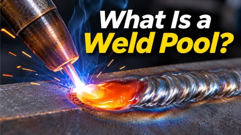
That front-panel dial looks simple until the rod sticks, the wire pushes into the plate, or molten metal runs ahead of your torch. I watch the puddle, the pool of liquid metal at the joint, more than the number on the screen because it tells me how the joint responds.
Say you’re patching a thin steel panel. You turn up the machine to flatten the weld, but the edge burns through instead. Why did more power make it worse? The missing piece may be how fast you’re moving or a gap between the parts.
The catch is that 100 amps doesn’t act exactly alike on every welding process. Wire size, electrode coating, metal thickness, and welding position all change what that number does. A setting that works flat on a bench may feel out of control on a vertical seam.
I’ll show you what amps change, where to start with stick (rod), MIG (wire-feed), and TIG (tungsten-electrode) welding, and when a small correction beats a big turn of the dial.
What Is Amperage in Welding, and What Does It Control?
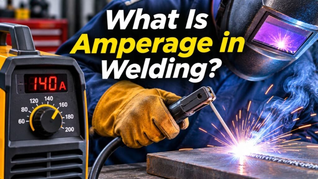
Amperage, measured in amps (A), tells you how much electric current moves through the welding circuit. With other conditions held steady, raising the current generally melts metal faster and makes a larger, more active weld pool.
The electrode carries current to the arc. The arc heats the base metal, which means the pieces being joined, and often melts added filler metal too. The liquid metal forms a molten weld pool, often called the puddle.
What matters is fusion, where the molten weld joins the base metal, and penetration, how far that melting reaches into the joint. On two overlapping steel strips, a bead (the line of deposited weld metal) can look smooth on top while barely joining the lower strip. Amps influence both, but they can’t make up for poor aim or joint preparation.
Key Takeaways:
- Amps describe current, not a fixed temperature.
- Judge the melted joint, not just the machine’s display.
- Current is one part of a sound weld, not the whole recipe.
Amperage vs. Voltage: Why Both Settings Matter
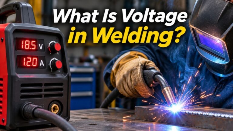
Amperage describes current flow, while voltage is the electrical push that drives it. Both affect arc power, but they behave differently depending on the machine and welding process.
On most stick and TIG welders, a constant-current (CC) power source holds current fairly steady as arc length changes. On a typical MIG welder, a constant-voltage (CV) power source holds the selected voltage fairly steady while current responds to wire-feed speed and arc conditions.
For example, lengthening a stick-welding arc changes its voltage even though the amps are still set on the front panel. On a conventional MIG machine, speeding up the wire feed usually raises welding current. Why does the same dial adjustment not work for both? Their power sources control different parts of the arc.
For a closer look at how arc length and electrical pressure interact, read about welding voltage.
Key Takeaways:
- Stick and TIG usually let you select current directly.
- Standard MIG setups link welding current to wire feed.
- Arc length, voltage, and travel speed can change the result even at a familiar amp reading.
How Much Amperage Do You Need for Welding?
The right amperage depends on the process, metal thickness, filler size, joint design, and welding position. Treat a chart as a starting point, then use the manufacturer’s instructions and a practice weld to make the final adjustment.
E7018 is a classification of low-hydrogen stick electrodes, meaning the coating is designed to help limit hydrogen-related cracking. The following examples include this rod type and common wire-welding setups.
| Welding setup | Approximate current | How to use the figure |
| Stick, E7018, 3/32-inch rod, electrode positive | 70–110 A | Published range for a specific E7018 product |
| Stick, E7018, 1/8-inch rod, electrode positive | 90–160 A | Published range for a specific E7018 product |
| MIG, .030-inch solid wire, 1/8-inch mild steel | Around 125 A | Initial estimate, adjusted through wire feed |
| TIG, electrode negative, 1/8-inch mild steel | Roughly 100–130 A | Working range, adjusted for joint and torch control |
Those figures are examples, not universal settings. The stick ranges reflect one manufacturer’s electrode current data; another brand or rod type may use a different band.
For solid-wire MIG on mild steel, a common rule of thumb is about one amp per .001 inch of plate thickness. That gets you in the ballpark for an initial setup, but it isn’t a formula for every metal or welding process.
Ever wondered why two pieces of the same thickness can call for different settings? A tight butt joint, where edges meet, behaves differently from a wide-gapped joint or a thick lap connection. Welding uphill or overhead also changes how easily you can hold the molten metal in place.
For structural work, pressure systems, or a job governed by a code, follow the approved welding procedure specification (WPS), the written instructions for that joint, rather than a general chart.
How to Set Amperage for Stick, MIG, and TIG Welding
Stick and TIG machines generally let you choose the welding current directly; with standard MIG equipment, you control it mainly through wire-feed speed. The best method depends on which process is making your arc.
Stick Welding: Start With the Rod
In stick welding (SMAW), a coated electrode melts and supplies filler metal. The coating, called flux, creates shielding and protective slag as the rod burns.
Read the rod packaging before setting the amps. Rod diameter, classification, and polarity, the electrical connection that determines the direction of direct-current flow through the arc, affect the recommended range. DCEP means direct current with the electrode connected positive, a common choice for E7018 but not the right choice for every rod.
I like to begin near the middle of a rod maker’s range for a flat practice weld, then adjust once I can hold a short, steady arc. Starting at the maximum just makes it harder to tell whether the technique is the problem.
Does a bigger rod fix a weak weld automatically? No. It needs the right current and enough access to the joint to melt both sides.
MIG Welding: Wire Speed Changes the Current
In MIG welding (GMAW), a motor continuously feeds wire through the gun. On a standard CV machine, faster wire feed usually means more current, while voltage helps shape the arc.
Wire speed is often shown in inches per minute (ipm). A thinner wire and a thicker wire will not produce the same current at the same feed speed, so use the chart inside the machine or the MIG parameter guide for the wire type and size.
I don’t fix a stubbing MIG wire by blindly cranking up feed speed. It may already be arriving too quickly for the arc to burn it off, so more feed can make the gun buck harder.
TIG Welding: Set a Ceiling, Then Control the Puddle
In TIG welding (GTAW), a tungsten electrode carries the arc but doesn’t normally melt into the weld. You add a separate filler rod when the joint needs it.
For many steel jobs, the machine uses DCEN, direct current with the electrode negative. AC (alternating current) is common for aluminum. If the setup has a foot pedal, set an upper current limit on the machine and use the pedal to control the heat during the pass.
What changes near the last inch of a TIG weld? The metal is already hot. I ease off the pedal as heat builds rather than holding the same output from start to finish, especially near a thin edge.
Key Takeaways:
- Check the electrode or wire label before changing current.
- A MIG wire-feed knob and a TIG foot pedal do different jobs.
- Adjust from a tested starting point, not from the machine’s maximum rating.
Signs Your Welding Amperage Is Too High or Too Low
Current that doesn’t suit the joint often leaves clues in the arc and the finished bead. These signs help narrow the problem, though arc length, travel speed, wire feed, and surface condition can produce similar faults.
If the Amperage Is Too Low
- A stick electrode repeatedly freezes to the work despite a proper arc length.
- The bead is tall or rope-like, with poor tie-in where the weld meets the plate.
- The metal sits on the surface without enough fusion along the joint.
Ever made a bead that looked neat until you checked its edges? That is why I focus on how the weld bead meets both sides, not on whether the center looks shiny.
If the Amperage Is Too High
- Thin material burns through or the joint edge melts away.
- Undercut, a groove melted beside the weld that wasn’t filled back in, develops along the edges.
- The puddle spreads so quickly that you lose control of its shape.
- The stick electrode may overheat before you finish using it.
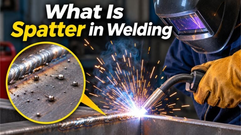
Extra weld spatter can occur with a bad setting, but it doesn’t prove the amps are too high. Voltage mismatch, shielding problems, dirty metal, and technique may be involved.
I change one setting at a time when troubleshooting. Otherwise, it’s too easy to fix one fault, create another, and end up back at square one.
A Safer Way to Dial In Welding Current
Pick a sensible setting from the proper chart, run a short practice weld, then make one small adjustment based on the result. That method gives you feedback without wasting a full project joint.
- Make the area safe before striking an arc. Don’t cut corners on protection. Wear a suitable welding helmet, dry gloves, flame-resistant clothing, and eye protection. Control fumes with suitable ventilation or local extraction, clear flammable material, and never weld on a closed tank or unknown container.
- Check the actual setup. Match the machine mode, polarity, electrode or wire, and shielding gas to the manufacturer’s directions. Clean the workpiece and attach the work clamp to sound metal.
- Account for the joint. Say you’re joining 1/8-inch angle iron to a thicker plate. The heavy side draws away heat faster than the thin side, so directing the arc evenly between them may not give equal melting. Watch both joint edges.
- Make a test bead on scrap that matches the job. Use the same metal, joint position, and fit-up, which means how well the parts meet before welding.
- Inspect, then make one change. Check the bead toes, the edges where weld metal meets the plate, and look for fusion. For practice pieces, cutting through a weld and examining the cross-section can reveal problems a smooth face hides.
What if the bead still doesn’t look right after a small adjustment? Check arc length, torch angle, travel speed, and, for MIG, wire stickout (the wire extending past the contact tip) before blaming the current again.
Key Takeaways:
- Use matching scrap before committing to the real part.
- Keep each adjustment small enough to learn from it.
- A clean surface and steady technique make amp changes easier to judge.
FAQs about what is amperage in welding
Is 100 amps enough to weld steel?
Yes, for many light steel jobs, depending on the welding process and joint. It may suit some small stick electrodes or TIG work on thinner sections, but it won’t cover every rod or thickness. Don’t judge a machine by that number alone; check its stated process and output range.
Can a 120-volt welder produce more than 120 welding amps?
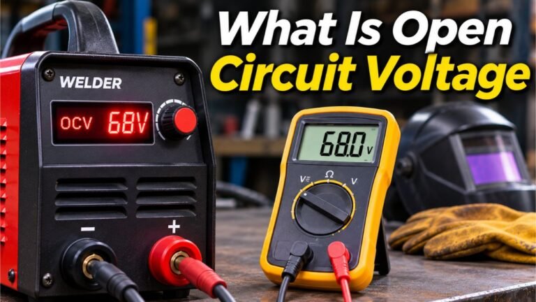
Yes. A machine’s 120-volt rating describes its input supply voltage, not its welding output current. The outlet’s breaker rating and the amperage delivered at the arc are different quantities too. Follow the welder’s input-power requirements and use a properly rated circuit.
Do AC and DC welding need the same amperage?
Not always. Some electrodes list separate ranges for AC and DC because the arc operates differently with each current type. The same rod classification may also behave differently across brands. Follow the exact electrode packaging and the machine’s polarity instructions instead of applying a fixed conversion.
Does a higher amp setting always make a stronger weld?
No. Strength depends on sound fusion, the joint design, suitable filler metal, and the weld’s finished size. Extra current can cause defects rather than improve strength. A weld carrying a significant load needs a suitable procedure and, where required, qualified inspection or testing.
Can I run my welder at its maximum amps nonstop?
Only if the machine is rated for continuous output at that setting. Duty cycle tells you how much of a 10-minute period the welder can operate at a stated load. For example, 30% duty cycle at 150 amps means three minutes of welding followed by the specified cooling time.
Get Your Welding Amperage Right on the Next Practice Bead
The best amp setting gives you a controllable puddle and a sound joint, not the biggest number the machine can deliver. I’d rather make a steady test pass at a reasonable current than chase a hotter arc and hope the metal behaves.
For your next practice session, pick one metal thickness, one filler or rod, and one joint type. Write down the machine mode and starting controls, then make a short pass. Record what the edges and back of the joint tell you, and change only the setting that needs attention.
Those notes will be more useful than memorizing a chart meant for a different machine or electrode. Once the arc feels steady and the joint shows good fusion, you’ve found a practical starting point you can return to. From there, build consistency before working on harder positions or heavier parts.