
How to Use a Stick Welder: Setup Steps and Troubleshooting Tips
A stick welder creates an electric arc between a flux-coated electrode and the metal workpiece, melting both into a joint. To use one safely, choose a compatible electrode, set the correct amperage and polarity, strike and control the arc, and remove slag between passes.
You usually notice the uncertainty when the rod sticks to the steel, the arc keeps going out, or the finished bead looks rough and full of holes. Those problems do not always mean the welder is defective; they often come from the wrong electrode, damp rods, poor grounding, incorrect settings, or an arc that is too long.
This guide explains how to use a stick welder from setup through cleanup, including machine connections, electrode selection, work preparation, body position, bead control, and troubleshooting. You will also learn which metals and thicknesses are practical for stick welding, what the common safety risks are, when a weld should be rejected, and when another process or a qualified professional is the better choice.
What stick welding does and when it is
Stick welding, formally called shielded metal arc welding or SMAW, uses a consumable electrode to create the weld. The electrode contains a steel or alloy core surrounded by flux; when the arc melts the rod, the flux produces shielding gases and a protective slag layer that help keep atmospheric oxygen and nitrogen away from the molten weld pool.
This process is useful because the equipment is relatively simple and portable. A stick welder can work outdoors, tolerate some surface contamination better than several gas-shielded processes, and weld carbon steel, low-alloy steel, stainless steel, and certain cast irons when the correct electrode and procedure are used.
It also has clear limitations. The operator must replace short electrodes frequently, chip away slag, and manage more spatter than is typical with a well-adjusted MIG setup. Thin sheet metal is especially difficult because the concentrated heat can burn through it before a stable bead forms.
Stick welding is commonly chosen for:
- Structural repairs and heavy steel fabrication
- Outdoor work where wind would disturb a shielding-gas process
- Farm, trailer, gate, and equipment repairs
- Rusty or less-than-perfect steel that can still be cleaned adequately
- Work sites where a compact power source and long welding leads are useful
It is not automatically the best option for every repair. If appearance, speed, thin-gauge control, or low cleanup is the priority, MIG or TIG may be more suitable. A welder should also avoid treating stick welding as a substitute for an engineered procedure on pressure vessels, lifting equipment, vehicle safety components, or load-bearing structures whose failure could injure someone.
How to use a stick welder: the equipment and materials to prepare
Before switching on the machine, gather the equipment needed to make a controlled weld rather than improvising after the arc starts. The exact requirements vary by welder and electrode, so the machine manual and electrode package remain the final authority for connection type, duty cycle, and settings.
- Stick welding power source: An AC, DC, or AC/DC machine with enough output for the electrode and metal thickness
- Electrode holder: The insulated clamp that grips the rod
- Work clamp: The return connection attached to clean metal on the workpiece or welding table
- Welding leads: Cables rated for the machine’s output and in good condition
- Electrodes: A suitable type and diameter for the base metal, position, polarity, and joint
- Welding helmet: An approved helmet with the correct dark shade for the current and process
- Protective clothing: Flame-resistant jacket or sleeves, long pants without cuffs, leather gloves, and leather boots
- Chipping hammer and wire brush: For removing slag and cleaning each pass
- Clamps and fit-up tools: To hold pieces still and maintain a consistent joint gap
- Ventilation equipment: Local exhaust or an appropriate respirator program when fumes cannot be adequately controlled
Inspect the electrode holder and work clamp for damaged insulation, loose connections, and exposed conductors. Replace compromised leads rather than wrapping serious damage with tape, and keep the cables away from sharp edges, hot metal, water, and vehicle traffic.
Check the machine’s duty cycle before a long weld. Duty cycle describes how long the welder can operate at a stated output during a standard period; exceeding it can trigger thermal protection or shorten component life. A machine that shuts down may simply need to cool, but repeated overheating can indicate excessive output, poor ventilation, or a fault.
Choose the electrode by metal, position, and power source
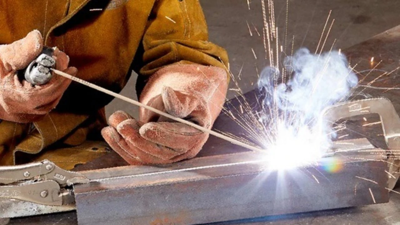
Electrode selection affects penetration, arc behavior, slag removal, weld appearance, and the strength and toughness of the finished joint. The rod diameter must also match the material thickness and the machine’s available amperage.
Common electrodes include:
- E6010: A forceful, deep-penetrating rod often used with DC electrode positive and root work, depending on the manufacturer’s instructions
- E6011: A versatile electrode that can operate on AC and, for many products, DC; it is often selected for repair work and less-than-perfect steel
- E6013: A smoother, easier-running general-purpose rod with moderate penetration, often useful for lighter fabrication
- E7018: A low-hydrogen electrode used when stronger, more ductile weld deposits and controlled hydrogen exposure matter; storage and handling are important
- Stainless and specialty electrodes: Rods formulated for stainless steels, cast iron, hardfacing, or other specific alloys
These descriptions are general, not permission to substitute one rod for another. Read the classification printed on the package, confirm the manufacturer’s recommended polarity, and check whether the electrode requires dry storage or rebaking.
The first two or three digits in many carbon-steel electrode classifications describe the approximate tensile-strength category and welding position, while the final digits identify coating and current characteristics. The classification system is useful, but the package instructions provide the practical amperage range and polarity for that specific product.
Match electrode diameter to material thickness
Use the smallest electrode that can make the required weld without excessive heat buildup. Larger rods deposit metal faster, but they also require more current and make it easier to overheat thin stock.
A 3/32-inch electrode is a common starting point for light and medium repair work, while 1/8-inch rods are widely used for thicker mild-steel joints. Larger diameters may be appropriate for heavy plate and long production welds, but only if the power source, joint design, and heat control support them.
The amperage printed on a rod package is a range, not a universal setting. Start near the lower or middle part of the recommended range, make a test bead on similar scrap, and adjust based on the arc and bead rather than relying on a number alone.
Set polarity and amperage before striking the arc
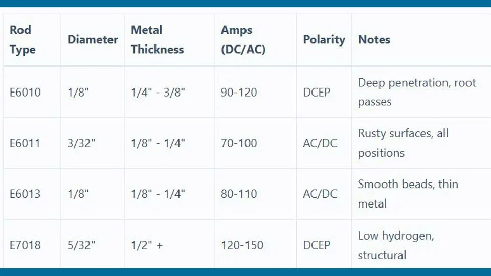
Connect the electrode lead and work lead according to the electrode manufacturer’s polarity recommendation. DC electrode positive, DC electrode negative, and AC can produce noticeably different arc characteristics, penetration, and heat distribution.
For many electrodes, the most common arrangements are:
- DC electrode positive (DCEP): The electrode is positive and the work clamp is negative; this often provides strong penetration and a stable arc for compatible rods.
- DC electrode negative (DCEN): The electrode is negative and the work clamp is positive; some electrodes and thin-material applications call for this arrangement.
- AC: Alternating current can be useful with machines and electrodes designed for it, especially where DC output is unavailable or arc blow is troublesome.
Do not assume every rod can run on every current type. A rod that lights easily on AC may behave poorly on DC, and using the wrong polarity can cause excessive spatter, shallow fusion, difficult arc control, or an unstable arc.
Turn the amperage down before making adjustments. Set the machine within the electrode package’s recommended range, then confirm the result on a clean piece of matching scrap. If the rod sticks repeatedly, increase current slightly or shorten the arc; do not immediately turn the machine to maximum.
Recognize the visual signs of an incorrect setting
Too little current often produces a weak, narrow bead with poor wetting at the toes. The electrode may drag against the work, the arc may extinguish, and slag can become difficult to remove because the weld does not stay fluid enough.
Too much current can create excessive spatter, undercut along the edges, a wide and difficult-to-control puddle, and unnecessary burn-through. The electrode may glow rapidly, and the bead can become sunken or irregular instead of slightly crowned and smoothly tied into both sides of the joint.
Arc length matters just as much as the dial setting. Hold the tip approximately the distance of the electrode’s bare metal core diameter from the work, then refine that distance according to the rod type and the manufacturer’s guidance.
Prepare and fit the metal before welding
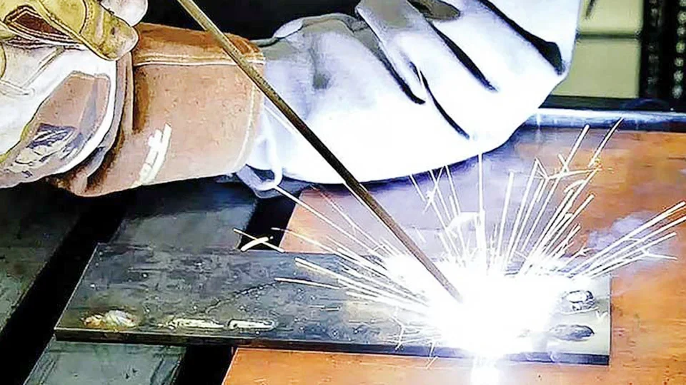
Clean the joint area with a grinder, wire brush, scraper, or suitable solvent process that leaves no residue. Remove paint, oil, moisture, heavy rust, mill scale, and galvanizing near the weld because contaminants can create porosity, fumes, inclusions, and incomplete fusion.
Never weld on a container, pipe, tank, or enclosed object that may contain flammable vapors or residues. Emptying it is not enough; safe preparation may require specialized cleaning, gas-free verification, ventilation, and a qualified hot-work procedure.
Cut the joint edges squarely and remove burrs. For thicker material, a bevel and root opening may be needed so the arc can reach the joint root instead of laying metal only across the surface.
Fit-up controls the amount of metal and heat required. Excessive gaps encourage burn-through and require more filler, while a joint closed tightly against an uneven edge can prevent root penetration.
Use clamps or tack welds to hold alignment, but plan the tack locations so they do not obstruct the weld path. Check for movement after each tack because heat causes steel to expand and contract, pulling the joint out of square.
For a butt joint, verify that the pieces are aligned and that the root opening is consistent. For lap and fillet joints, make sure the overlapping surfaces or inside corners are in firm contact where practical; a hidden gap can trap contaminants and reduce the effective weld area.
Follow a safe stick-welding setup sequence
Safety must be established before the first arc, not added after a problem appears. Stick welding creates ultraviolet radiation, hot slag, molten metal, fumes, electrical hazards, fire hazards, and enough noise or impact to require appropriate protection.
- Clear the work area. Remove paper, solvents, fuel, sawdust, rags, and other combustibles from the arc zone. Shield nearby people and equipment from sparks and ultraviolet light.
- Provide ventilation. Position local exhaust close enough to capture fumes without disturbing the arc. Do not weld coatings or plated material until the hazards have been removed or controlled.
- Inspect the machine. Confirm that the power cord, plugs, leads, holder, clamp, and controls are undamaged. Keep the power source dry and properly grounded as required by its instructions.
- Put on protective gear. Wear the helmet before the arc starts, along with safety glasses, hearing protection when needed, flame-resistant clothing, insulated gloves, and sturdy leather footwear.
- Secure the workpiece. Clamp the metal so it cannot fall, rotate, or shift when heated. Do not rely on your hand or foot to hold a workpiece.
- Attach the work clamp. Connect it to bright, clean metal as close to the weld as practical. A clamp attached over paint, rust, or a loose table connection can make the arc unstable.
- Connect the electrode lead. Insert the electrode firmly into the holder at a comfortable angle, keeping your gloved hand away from the bare end.
- Choose polarity and amperage. Follow the electrode packaging and machine instructions, then make a test bead on scrap.
Keep your body insulated from the work and avoid welding in wet conditions. Do not touch the electrode or metal with bare skin when the machine is energized, and remove the electrode from the holder when the job pauses.
Electric shock can occur when a person completes a circuit through the electrode, workpiece, damp clothing, or surrounding metal. Damaged insulation, wet gloves, standing water, and cramped conductive spaces make the risk worse.
How to use a stick welder to start and control the arc
Strike the arc with either a light scratching motion or a brief tapping motion, depending on your preference and the electrode. As soon as the arc starts, lift the rod just enough to establish the correct arc length and move into the weld path.
Dragging the rod directly along the work usually causes it to stick unless the electrode is a specialized drag-type product. Holding it too far away creates a long arc, which increases spatter, reduces shielding, and can produce an irregular or porous bead.
Use the correct body position and travel angle
Arrange your stance before striking the arc so you can move smoothly through the full joint. Keep your shoulders relaxed, brace your welding hand if possible, and position the helmet so you can see the puddle without twisting your neck.
A small travel angle, often described as a drag angle, lets the electrode point slightly back toward the completed weld. The exact angle depends on the electrode and joint position, but a modest angle is generally easier to control than holding the rod nearly perpendicular or laying it too far over.
Keep the electrode centered in a fillet joint so the arc fuses both legs. In a butt joint, follow the joint line and watch the molten pool rather than the bright arc alone. The puddle shows whether the edges are melting, whether the bead is filling the joint, and whether slag is trying to run ahead of the arc.
Control travel speed and weave width
Move too slowly and the bead becomes excessively wide and high, with more heat input and a greater chance of undercut or burn-through at the edges. Move too quickly and the bead becomes narrow, poorly tied in, or visibly discontinuous.
For many joints, a straight or only slightly oscillated bead provides better control than a broad weave. If a weave is necessary to fill a joint, pause briefly at each side to fuse the toes, keep the center moving, and limit the width according to the electrode instructions and the joint position.
Watch the molten weld pool rather than chasing the electrode tip. The pool should advance smoothly, with the edges washing into the base metal and the slag following behind. A steady buzzing or frying sound, where appropriate for the electrode, is generally easier to maintain when arc length and travel speed are consistent.
This distinction matters when answering “how to use a stick welder”.
When the electrode becomes short, stop before the holder reaches the work. Break the arc by lifting away, release the stub safely, and install a new rod. Restart slightly ahead of the crater, then work back into it so the new bead overlaps sound metal.
Remove slag and inspect every weld pass
Allow the weld to cool enough for safe handling, then remove slag with a chipping hammer and wire brush. Wear eye protection because slag can fracture and fly in unexpected directions, even when it appears loose.
Slag is not merely dirt. It protects the cooling weld while the arc is active, but any residue left between passes can become an inclusion that weakens the joint or prevents fusion.
After cleaning, inspect the bead before depositing another pass. Look for:
- Cracks running along or across the bead
- Pinholes or clusters of small holes that suggest porosity
- Visible slag trapped in grooves or between passes
- Undercut along either edge of the weld
- Cold lap, where metal rolls over the base material without fusing into it
- Incomplete fill, an open crater, or a bead that stops short of the joint
- Uneven width, excessive spatter, or abrupt starts and stops
A sound-looking surface does not prove that the weld has adequate internal penetration. Critical welds may require inspection methods, procedure qualification, or professional testing beyond visual examination.
For multipass work, alternate the starting points when practical and keep each layer clean. Avoid burying a visible defect under a later pass; grind or remove questionable metal and repair it while the area remains accessible.
Troubleshoot a stick welder that will not run smoothly
Most beginner problems have a small number of causes: incorrect current, poor electrical contact, unsuitable polarity, an unstable arc length, damp electrodes, contaminated metal, or inconsistent hand movement. Change one variable at a time so the result tells you what fixed the problem.
Why the electrode keeps sticking
An electrode sticks when the arc cannot maintain enough heat to keep the tip and workpiece separate. The usual causes are amperage set too low, an arc held too short, a poor work-clamp connection, damp contamination, or a rod that is too large for the machine.
- Increase amperage modestly within the electrode’s recommended range.
- Clean the clamp location and move the work connection closer to the joint.
- Use a smaller electrode if the material or power source is limiting current.
- Lift and restrike rather than twisting the stuck rod forcefully.
- Check that the polarity matches the electrode package.
If the holder becomes hot, stop and inspect the connection. A loose cable lug, damaged holder, or poor contact can create resistance and heat independent of the arc.
Why the arc is unstable or keeps going out
An unstable arc can result from a weak ground path, wrong polarity, a contaminated joint, low input power, or inconsistent arc length. Start by cleaning the work connection and the welding area, then verify the electrode and current settings.
Some electrodes are more forgiving than others. An E6013 may feel easier for a new operator on suitable mild steel, while a deep-penetrating rod may demand more precise control and a stronger power source.
Why there is excessive spatter
Spatter increases when the current is too high, the arc is too long, the polarity is wrong, or the electrode is damp or contaminated. It can also increase when the rod angle changes constantly or the work clamp connection is unreliable.
Shorten the arc, reduce current slightly, and practice a steady travel motion on scrap. Do not confuse a small amount of normal spatter with a setting that is throwing molten droplets far beyond the joint.
Why the weld has holes or porosity
Porosity is gas trapped in the solidifying weld. Moisture, oil, paint, rust, damp electrodes, inadequate shielding from the flux, and an excessively long arc are common contributors.
Clean the base metal more thoroughly, store rods as directed, and keep the arc short. If the problem appears only at the start or end of a weld, improve the starting technique and fill the crater instead of breaking the arc abruptly.
Why the weld lacks penetration or fusion
Insufficient penetration can come from too little current, excessive travel speed, an electrode that is too large or unsuitable, an incorrect joint gap, or an angle that directs heat away from the root. Surface metal may appear present while the joint remains only partially fused.
Use a properly prepared joint, adjust the heat within the electrode’s range, and slow down enough for the pool to reach both edges. On thick steel, a single surface pass may not be adequate; beveling and multiple controlled passes may be required.
Why the weld is undercut or burned through
Undercut is a groove melted into the base metal beside the bead and left unfilled. Excessive current, a long arc, fast travel, or dwelling too long at the center of a weave can cause it.
Reduce current slightly, shorten the arc, and pause at the toes rather than racing across them. Burn-through usually means the heat input is too high for the thickness or joint gap, so use a smaller electrode, lower current, shorter segments, or a better-supported fit-up.
Why the slag is difficult to remove
Slag that does not release readily may indicate the wrong electrode technique, insufficient cleaning, excessive heat, or slag trapped in an uneven bead. A properly deposited pass often allows the slag to crack or lift with moderate chipping.
Do not gouge aggressively into a questionable weld and assume the remaining surface is sound. Brush thoroughly, inspect the profile, and remove trapped material before making the next pass.
Understand electrode storage, maintenance, and cleanup
Moisture control matters most with low-hydrogen electrodes such as many E7018 products. Store them exactly as specified by the manufacturer, keep opened packages protected, and do not assume that a household oven or improvised heater is a safe replacement for approved storage and conditioning equipment.
Moist electrodes can contribute to porosity, arc instability, and hydrogen-related cracking under conditions where the weld and base metal are susceptible. If rods have been exposed to damp air or the package instructions require controlled reconditioning, follow the stated procedure or choose a properly stored replacement.
After welding, switch off the machine and disconnect power when required for the equipment and work situation. Allow hot metal to cool in a controlled location, mark it as hot if other people are nearby, and check the work area for smoldering material before leaving.
Clean slag and spatter from the workpiece and tools. Keep the welder’s ventilation openings clear, coil leads without sharp kinks, and store the holder where it cannot contact a grounded object or create an accidental arc.
Know which metals and jobs require extra caution
Clean mild steel is the most forgiving material for learning. Stainless steel requires a compatible stainless electrode and careful contamination control; using carbon-steel tools on stainless can introduce iron contamination that later causes rust or poor appearance.
Cast iron is difficult because it is brittle and responds poorly to uncontrolled heating and cooling. Repairs may require specialized electrodes, preheating, short weld segments, peening or cooling controls, and a detailed procedure rather than a casual bead over the crack.
Galvanized steel presents a serious fume hazard because the zinc coating can produce harmful fumes when heated. Remove the coating only with an appropriate method, provide effective ventilation, and use a qualified hot-work approach; never rely on simply wearing a basic dust mask.
Painted, plated, oily, or unknown alloys can also release hazardous fumes. If the coating or base metal cannot be identified and safely prepared, stop and obtain expert guidance.
Do not weld near flammable liquids, pressurized cylinders, combustible insulation, or concealed spaces without a suitable fire-prevention plan. Sparks can travel farther than expected through openings, and a fire can begin after the visible welding has stopped.
Decide when stick welding is the wrong process
Stick welding is often a strong choice for thick steel, outdoor repair, and portable work, but process selection should follow the material and quality requirement. For thin automotive panels or sheet metal, MIG with appropriate wire and settings may offer easier control and less burn-through.
TIG can provide cleaner, more precise welds on stainless steel, aluminum, and thin materials, but it requires more coordination and equipment. Stick welding generally cannot weld aluminum effectively with ordinary steel electrodes, and specialized processes are usually preferred.
Choose a different approach or seek professional help when:
- The joint supports people, vehicles, lifting loads, pressure, or critical machinery.
- The base metal, coating, or previous repair is unknown.
- The work involves a tank, pipe, vessel, fuel system, or enclosed container.
- The material is too thin for the available electrode and machine.
- You cannot establish adequate ventilation or fire control.
- The weld must meet an engineered specification, code, inspection requirement, or certified procedure.
- Cracks, lack of fusion, distortion, or repeated defects remain after basic troubleshooting.
Professional assistance is not limited to hiring someone to run the bead. A qualified welder or engineer may need to identify the alloy, select the joint design, determine preheat and interpass controls, specify filler metal, and verify the finished weld.
Practice a controlled first weld
Start on clean mild-steel scrap similar in thickness to the intended project. A flat-position fillet or butt joint is easier to observe than an overhead or vertical weld, and it lets you focus on arc length and travel speed.
- Cut and clean two pieces of scrap.
- Clamp them in a simple joint with consistent alignment.
- Select a small, compatible electrode and set polarity according to its package.
- Make a short bead while watching the puddle.
- Let it cool, remove slag, and inspect both toes and the crater.
- Adjust only one setting or technique variable.
- Make another bead and compare the result.
Practice restarting electrodes, maintaining a short arc, and stopping without leaving an unfilled crater. Try straight beads before learning wide weaves, and practice on horizontal work before moving to vertical or overhead positions.
A useful test is to break or cut a practice joint after welding, when doing so is safe and the project is noncritical. The exposed cross-section can reveal lack of fusion or penetration that the surface does not show, although destructive testing of scrap does not qualify a weld for a critical application.
Final takeaway for using a stick welder safely and effectively
Learning how to use a stick welder comes down to matching the electrode and polarity to the material, making a clean and secure setup, controlling a short arc, and inspecting every pass after slag removal. Begin with clean mild-steel scrap, use conservative settings, and change one variable at a time when troubleshooting.
The major limits are thin material, hazardous coatings, damp electrodes, poor ventilation, and joints whose failure could cause serious harm. If the work is structural, pressure-related, contaminated, or beyond your ability to inspect confidently, stop and involve a qualified welding professional before placing it in service.